I've been wondering about this. I've been reading about mosfets at university and I think I have a decent understanding of them. Take this class A amp circuit as an example:
http://i50.tinypic.com/10hugp5.png
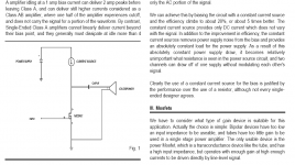
Don't mind any of the component values. When I look at many class A amp designs out there they seemed to be littered with components and I often see a minimum of 5 transistors used in all sorts of ways, but I'm wondering why? I can see some problems with the circuit I linked though like the output cap and current source, but if we assume an ideal output cap and an ideal current source, what is flawed with this design? What kind be done to further increase the quality of the sound?
http://i50.tinypic.com/10hugp5.png
Don't mind any of the component values. When I look at many class A amp designs out there they seemed to be littered with components and I often see a minimum of 5 transistors used in all sorts of ways, but I'm wondering why? I can see some problems with the circuit I linked though like the output cap and current source, but if we assume an ideal output cap and an ideal current source, what is flawed with this design? What kind be done to further increase the quality of the sound?
I've been wondering about this. I've been reading about mosfets at university and I think I have a decent understanding of them. Take this class A amp circuit as an example:
http://i50.tinypic.com/10hugp5.png
Don't mind any of the component values. When I look at many class A amp designs out there they seemed to be littered with components and I often see a minimum of 5 transistors used in all sorts of ways, but I'm wondering why? I can see some problems with the circuit I linked though like the output cap and current source, but if we assume an ideal output cap and an ideal current source, what is flawed with this design? What kind be done to further increase the quality of the sound?
What is the load requirement? 100 Ohm? Is that a headphone?
There are many already. Search for Pass Labs' Bride of Zen.
With one device, you rely on device transconductance, limited by input capacitance to charge. For speaker amplifier (around 4W) search for ZCA.
When you can accept the limited power of a single device (and the associated high output impedance), what you need is to work out the bad power supply rejection. Usually the power supply needs to be complex.
Member
Joined 2009
Paid Member
Well I was thinking of an amp for hifi speakers so 4-8Ohms then I guess. I'm not here to find a design I could make, I'm here to learn about the theory behind it and if/why a more complex design is better.
I'm aware of the bad PSRR, but won't a voltage regulator massively improve that? Heck, two voltage regulators in series would give a ridiculous PSRR, won't it? But what if we assume that the power supply is an ideal DC voltage source aswell?
I'm aware of the bad PSRR, but won't a voltage regulator massively improve that? Heck, two voltage regulators in series would give a ridiculous PSRR, won't it? But what if we assume that the power supply is an ideal DC voltage source aswell?
Appears okay on first glance, except you would likely want to insert a mosfet source degeneration bias resistor of appropriate value.
Thats to get a little feedback in order to keep the operating point steady, right? Won't having R3 connected to drain sort of do that? I don't understand why the amp would need feedback though, what would cause the operating point to change other than if the bias current were to change? But I'm assuming an ideal current source

Well I was thinking of an amp for hifi speakers so 4-8Ohms then I guess. I'm not here to find a design I could make, I'm here to learn about the theory behind it and if/why a more complex design is better.
I'm aware of the bad PSRR, but won't a voltage regulator massively improve that? Heck, two voltage regulators in series would give a ridiculous PSRR, won't it? But what if we assume that the power supply is an ideal DC voltage source aswell?
Class-A is not efficient. You may need current more than an LM317 can provide. Then you start to add bypass transistor, complicating the power supply...
If I want to create a single transistor amplifier, I will start with finding the suitable device for the job (high transconductance, low capacitance, sufficient current or power capability). Lateral fet (2SK1056 family) is known to have low capacitance and hence requires less current than VFET (IRFP240 family).
The higher the current, the better the quality of the sound (lower distortion, more linear). Then you need complex (read: big) heatsinking.
Everything else you seem already know how to do it, no?
Plecto, I believe that when you read the PDF documentation of BOZ along with other Zen amp documentations, you will not be back with similar questions
Thanks to Nelson Pass who made amplifier building so easy to understand.
Thanks to Nelson Pass who made amplifier building so easy to understand.
Attachments
Last edited:
I have read the Zen amp documentation (that's the one that made me interested in this ) and the death of zen documentation. I haven't really found my answers in those papers though as they don't explain the reason for many amp designs to have 200 components in them. The guy who made death of zen seemed to believe that BJT's was more linear than mosfets, but i'm not sure how audiable this is?
The point of the thread isn't heatsinking, power dissipation or how the power supply is made, I'm just focused on the power stage that I linked in the opening post, this is purely theoretical.
So lets say I buy one of those mosfets with high transconductance, low capacitance and sufficient current or power capability and make the design I linked with an ideal current source, ideal DC voltage source and an ideal output cap. Would this then have a distortion of way under 1% and it would be good to go as a high-end amplifier with as good of a sound as you can ever get from an amp?
) and the death of zen documentation. I haven't really found my answers in those papers though as they don't explain the reason for many amp designs to have 200 components in them. The guy who made death of zen seemed to believe that BJT's was more linear than mosfets, but i'm not sure how audiable this is?The point of the thread isn't heatsinking, power dissipation or how the power supply is made, I'm just focused on the power stage that I linked in the opening post, this is purely theoretical.
So lets say I buy one of those mosfets with high transconductance, low capacitance and sufficient current or power capability and make the design I linked with an ideal current source, ideal DC voltage source and an ideal output cap. Would this then have a distortion of way under 1% and it would be good to go as a high-end amplifier with as good of a sound as you can ever get from an amp?
I may have missed it in earlier replies, but that Power Amplifier has a maximum output of 0.7W into an 8r0 load.
If you try to drive an ordinary 8ohms speaker at -20dB (average level ref maximum power) to avoid clipping then you will just about have to clamp the speaker to your ear to hear it. Am I allowed to exaggerate slightly?
If you try to drive an ordinary 8ohms speaker at -20dB (average level ref maximum power) to avoid clipping then you will just about have to clamp the speaker to your ear to hear it. Am I allowed to exaggerate slightly?
Last edited:
Thats to get a little feedback in order to keep the operating point steady, right? Won't having R3 connected to drain sort of do that? I don't understand why the amp would need feedback though, what would cause the operating point to change other than if the bias current were to change? But I'm assuming an ideal current source
A source resistor would work to stabilize the bias current against the D.C. bias voltage variation applied by the feedback resistors, making the setting of the operating point less sensitive.
Last edited:
I may have missed it in earlier replies, but that Power Amplifier has a maximum output of 0.7W into an 8r0 load.
If you try to drive an ordinary 8ohms speaker at -20dB (average level ref maximum power) to avoid clipping then you will just about have to clamp the speaker to your ear to hear it.
Well I have made that amp with a output power of around 15W I believe, my transformers output voltage limited it from going higher. Why would it be limited to 0.7W? I said disregard all component values in the opening post.
.... this is purely theoretical. ....
Hi, really good amplifier designs are purely practical, rgds, sreten.
The DoZ is a good design, for reasons very apparent in the article.
I have read the Zen amp documentation
Okay.
I haven't really found my answers in those papers though as they don't explain the reason for many amp designs to have 200 components in them.
From Zen amp documentation: "Simplicity is a common element of the best and most subtle designs. It is preferred for purely aesthetic reasons, but also because fewer elements color the sound less, and lose less information. Many audiophiles, including myself, are willing to sacrifice other areas of performance to achieve the intimacy with the sound available through a simple circuit. An amplifier should be simple, but it also must be linear. Some measure of distortion in an amplifier is unavoidable and forgivable if it is of a less offensive type."
So simple class-A amps have high distortion, but often they are of less offending type. Complex circuit, must be made accurately, but still, they sound different. Less intimacy. Worse, TIM/PIM.
The guy who made death of zen seemed to believe that BJT's was more linear than mosfets, but i'm not sure how audiable this is?
I don't understand the point of "DOZ". It is based on a very old design known by everyone, also inspiration for many including NP. So when Zen was created, NP must have been very familiar with JLH1969. But suddenly there is this death of Zen
Of course mosfet is not linear. From their chart we know that it must operate at high bias to be sufficiently linear.
So lets say I buy one of those mosfets with high transconductance, low capacitance and sufficient current or power capability and make the design I linked with an ideal current source, ideal DC voltage source and an ideal output cap. Would this then have a distortion of way under 1% and it would be good to go as a high-end amplifier with as good of a sound as you can ever get from an amp?
Yes you can. The higher the gain, the worse the distortion (because high transconductance device are not linear because they are not intended for audio). So you should aim for the perfect "first watts" and consequently use sensitive speaker to get the required SPL.
F2J for example, is single ended and is extremely low distortion.
Last edited:
F2J for example, is single ended and is extremely low distortion.
Yep, I hardly ever give my heat sinks a chance to cool down
Thanks for the replys, I'm starting to get it. So the reason for my design not beeing ideal is because of the unlinearity of the mosfet? If I were to choose a decent mosfet with good charecaristics for this design, a decent current source design and a voltage regulator on the input, what kind of distortion would I expect? The output electrolytic cap might still be the bottleneck here perhaps? Higher gain can be achieved by choosing a decent op-amp as an input stage, right?
If I were to choose a decent mosfet with good charecaristics for this design, a decent current source design and a voltage regulator on the input, what kind of distortion would I expect?
I think all HEXFET are designed not for audio (mostly switching), so you cannot expect perfect linearity required by audio. IRFP240, IRFP460, IRFP150 etc are about the best we can get (about the best compromise between power, transconductance and capacitance).
The ZCA is an example of single ended 1 stage amplifier utilizing lateral fet intended for audio (Hitachi 2SK1056 and its family). Around 4W. Distortion is "terrible" but of non offending type so we can still get the charm of simple stage amplifier.
VladimirK, a DIYA member, have had access to Russian mosfets with better specs. But still, imo one stage is not optimum for average power requirement.
Imo, 3 or 2 stage is optimal for domestic power requirement of average speaker sensitivity.
ZenV4 is Zen with input buffer. ZenV9 with extra "stage". Imo, Aleph J (I prefer the Babelfish variation) is the best compromise between simplicity, power, drive and distortion.
The output electrolytic cap might still be the bottleneck here perhaps? Higher gain can be achieved by choosing a decent op-amp as an input stage, right?
I have never thought an output cap as a bottleneck. Even if it creates distortion, it is of non offending type.
Opamps are made of complex circuit. So by using it we lose the charm of simplicity. Many cannot hear the "opamp" sound, but I have never liked opamp based designs.
Most opamps cannot deliver sufficient current and voltage swing. So 1 opamp plus 1 stage SE is useless here.
Opamps are made of complex circuit. So by using it we lose the charm of simplicity. Many cannot hear the "opamp" sound, but I have never liked opamp based designs.
Most opamps cannot deliver sufficient current and voltage swing. So 1 opamp plus 1 stage SE is useless here.
I can't see the voltage beeing a problem, it's not a problem for an op-amp to output 20V or so. Some audio op-amps like the LM4562 has vanishingly little distortion, I can't see why this would affect it.
I think all HEXFET are designed not for audio (mostly switching), so you cannot expect perfect linearity required by audio. IRFP240, IRFP460, IRFP150 etc are about the best we can get (about the best compromise between power, transconductance and capacitance).
What if linearity (and sufficient current and power dissipation of course) is the highest priority, completely sacrifice gain and input capacitance? The LM4562 can be supplied with +-17V (or 34V single ended) and can supply an output current of 26mA into a 600Ohm load, shouldnt this be an acceptable input stage?
If one single stage mosfet alone (in follower configuration) is acceptable to many people, addition of input stage will not make it worse. So of course it will "work".
One key secret of good sounding mosfet amp is current drive and an opamp wont help. The problem to my opinion is... When you choose the high distortion simple circuit, you sacrifice many factors to get that "tubey" sound. And most but all opamps that I have used will spoil it. I haven't tried or heard the new LME opamps tho...
BTW I'm still looking for a chance to build class-A buffer (such as being designed by Lineout) to be driven directly by special opamps (that I own but never been tried, up to 2000V/us devices). That's a better option than driving a follower, but I cannot see reason why it will be paramount.
Thats to get a little feedback in order to keep the operating point steady, right? Won't having R3 connected to drain sort of do that? I don't understand why the amp would need feedback though, what would cause the operating point to change other than if the bias current were to change? But I'm assuming an ideal current source
Your schematic suggests that you are far from discussing the intricacies of MOSFET capacitances and GM since it has a number of glaring problems.
For one, the imput impedance is less than 50 ohms (possibly considerably less). The input caps at 1uF will make the lower cut-off frequency somewhere in the kHz region. Even worse with an 8 ohm load and output cap of 1uF. Closing the bias point for both AC and DC from the drain also implies feedback, which makes actual gain heavily dependant on the output impedance of the source (once you get into frequencies the 1uF input cap will actually make pass through!).
As for your questions, high GM MOSFETs also tend to come woth high input capacitance and you want this minimized. GM rises as drain current rises, and in most cases linearity improves, so running at high bias (even higher than the lowest required for class A) has some advantages (obvious disadvantage being heat). Getting Vgd lower than some 5V or so for most vertical types runs input capacitance into a heavily nonlinear region, the same for lowering Vds below 5V or so.
- Status
- This old topic is closed. If you want to reopen this topic, contact a moderator using the "Report Post" button.
- Home
- Amplifiers
- Solid State
- Can a very simple class A amp produce great sound?