There is nothing wrong with using ground-planes in audio circuits (in a way the metal chassis is one), but you must take care that you seperare (physically and electrically) your digital from analogue circuitry
I rarely use ground/supply planes unless I work with high gain and/or high frequency stuff. E
I rarely use ground/supply planes unless I work with high gain and/or high frequency stuff. E
There is nothing wrong with using ground-planes in audio circuits (in a way the metal chassis is one), but you must take care that you seperare (physically and electrically) your digital from analogue circuitry
I rarely use ground/supply planes unless I work with high gain and/or high frequency stuff. E
I'm talking pure analog audio amps and line level filters, no dacs. And this will potentially be without a metal chassis, just ground pcb plane.
The biggest problems are caused by poor grounding and ground loops.
My first audio mixer hummed like mad coz I just laid the pcb out as it came.
The pulses of current into the smoothing capacitors were also getting into the audio ground. I completely separated the power supply and audio grounds and the hum completely disappeared.
My first audio mixer hummed like mad coz I just laid the pcb out as it came.
The pulses of current into the smoothing capacitors were also getting into the audio ground. I completely separated the power supply and audio grounds and the hum completely disappeared.
To achive the lowest distortion, noise and hum, audio amplifiers general use carefully designed PCB trace routing, to eliminate loops and contaminating currents (such as output stage currents in the 0V rail passing through 0V rail for the input stage).
I understand that, but that doesn't really help answer my question. Is it impossible to achieve low noise and hum with a ground plane?
The biggest problems are caused by poor grounding and ground loops.
My first audio mixer hummed like mad coz I just laid the pcb out as it came.
The pulses of current into the smoothing capacitors were also getting into the audio ground. I completely separated the power supply and audio grounds and the hum completely disappeared.
My power supply is on a completely different board than my amp and other circuitry.
I understand that, but that doesn't really help answer my question. Is it impossible to achieve low noise and hum with a ground plane?
Depending how you connect your ground line to the ground plane you could make it worse.
I would lay out the pcb as per my previous post then use separate power plane for power and audio ground and star ground them in one place.
I'm talking pure analog audio amps and line level filters, no dacs. And
this will potentially be without a metal chassis, just ground pcb plane.
Hi,
Without a metal chassis you'd probably need a double
sided PCB with one side being mainly the ground plane.
rgds, sreten.
My power supply is on a completely different board than my amp and other circuitry.
Sure ground planes are fine. I use them in my preamp designs after hand routing(Pass XP30). Good pcb software allows setting up rooms for sections and isolation. They can also assist mechanical stress issues.
I dont believe that was his question (do I NEED a ground plane), he asked why people dont use them. its not like they are a luxury, people seem to avoid them for similar reasons they avoid SMD parts, because they 'suck the life out of the sound'...I believe your question was anwered. You do not need a ground-plane, just good design technique to get clean amplification. E
its the typical avoidance of modern design and building techniques by a certain element, there is all sorts of folklore about it. planar capacitance destroys the sound etc. with careful layout I dont even believe you even need to have separate ground planes, to me that can add its own problems.
just as with everything, recognize where the loops are and keep them as tight as possible. you can keep noise and high slewing currents away from delicate areas quite effectively by cutting slots in the plane
Last edited:
To achive the lowest distortion, noise and hum, audio amplifiers general use carefully designed PCB trace routing, to eliminate loops and contaminating currents (such as output stage currents in the 0V rail passing through 0V rail for the input stage).
Yes, since a sensible way to set up the grounding is a star or a star on star, a single ground plane is less practical. Think of it as multiple ground planes. If you have more than one circuit on a PCB, you would want to have a seperate branch of ground plane for that circut that eminates from one of the star points. For example, you would want to place the output transistor decoupling capacitor ground return currents around the ground for the input stage and signal source ground nodes. Keep separate large ground currents from small ground currents.
I dont believe that was his question (do I NEED a ground plane), he asked why people dont use them. its not like they are a luxury, people seem to avoid them for similar reasons they avoid SMD parts, because they 'suck the life out of the sound'...
its the typical avoidance of modern design and building techniques by a certain element, there is all sorts of folklore about it. planar capacitance destroys the sound etc. with careful layout I dont even believe you even need to have separate ground planes, to me that can add its own problems.
just as with everything, recognize where the loops are and keep them as tight as possible. you can keep noise and high slewing currents away from delicate areas quite effectively by cutting slots in the plane
I disagree about SMDs. The lower cost of production makes them the future, get used it.
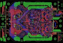
") Here is the latest version of my stereo module PCB. It is almost ready but I have to leave town for a couple weeks so it will have to wait til after. I believe that you do not need lots of current until you get to the final stages in a power amplifier so I chose components that are suited for lower current operation. Therefore, it uses plenty of SMDs, because how else are you going to cram this much circuitry into a PCB area of 6"X4.5"? Here is the first version, first build, and the same amp I'm listening to right now, sound is superb!. It worked so well that I didn't bother making the other two PCBs I have for the first version. The whole idea is a Hi-Fi stereo amplifier module where all that is needed is an enclosure, and a power transformer. The daughter board cutouts are marked, I'll do that though because to get a board house to do cutouts on a prototype run is expensive.
Here is the latest version of my stereo module PCB. It is almost ready but I have to leave town for a couple weeks so it will have to wait til after. I believe that you do not need lots of current until you get to the final stages in a power amplifier so I chose components that are suited for lower current operation. Therefore, it uses plenty of SMDs, because how else are you going to cram this much circuitry into a PCB area of 6"X4.5"? Here is the first version, first build, and the same amp I'm listening to right now, sound is superb!. It worked so well that I didn't bother making the other two PCBs I have for the first version. The whole idea is a Hi-Fi stereo amplifier module where all that is needed is an enclosure, and a power transformer. The daughter board cutouts are marked, I'll do that though because to get a board house to do cutouts on a prototype run is expensive. The board includes the power supply, and output speaker relays with logic that switches the amp from standby mode to active. Standby mode de-energizes the output stage circuits via a couple power Trench fets so the amp draws no bias. Included is DC detection/protection, output stage fuse protection that triggers the logic to standby mode for short circuit protection. In addition it has clipping detection, and thermal management including a DC fan with control circuit and thermal shutdown for extreme temperatures. The amplifier circuits are quite unique too but that discussion is for another day.
Attachments
I haven't looked at many audio amplifier pcbs but it seems almost none of them use ground planes. Are they typically a bad idea in audio amplifiers? It would definitely make routing a lot easier with them.
Ground planes only exist on 4 or more layer boards - they'd be internal hence invisible. A ground fill is a different thing and perhaps that's your meaning here. Ground fills are sometimes used but in general they're worse for the sound because they make connections to GND seem easy - just link to the fill and you're done. In reality grounding is a major part of the sound and if you don't pay attention to the current flows into GND then the sound won't be optimal.
here is an answer ...
ground plane in audio circuits like pre or amp involve a couple of conditions
A) there is a a good chance that the ground traces will interact with the rest of the circuit and behave as inductor or capacitance be tween traces ...Sophisticated design and proper equipment to measure this behavior might solve the problem partially .
B) depending on the Input Z or the output Z many of audio circuits require clean ground as described above or even better a star ground .implementing a ground plane will defeat both above needs and will end up in ""all around ground tubish style "
Finally having a ground plane that lays around circuits separated though electrically from real ground will probably help no where and/or cause complications .
then again i tried in one of my preamplifier to create a pcb that has a ground plane which is actually connected to case i ground while signal ground remains floating all the way through . As we speak this is working perfectly for a couple of years for a pre that can do 200khz sine wave and almost 100 square and there is no audible noises but still this needs to be double verified from instruments .
Kind regards
sakis
Ground planes only exist on 4 or more layer boards - they'd be internal hence invisible. A ground fill is a different thing and perhaps that's your meaning here. Ground fills are sometimes used but in general they're worse for the sound because they make connections to GND seem easy - just link to the fill and you're done. In reality grounding is a major part of the sound and if you don't pay attention to the current flows into GND then the sound won't be optimal.
You are generalizing a lot here.
Ofcourse there is possible to have Groundplane on a 2-layer board.
Quite simply by routing the boards as we did back in the 80-70-60.
All routing on one side, and a groundplane on the other.
Filling was often used too back then, especially on DIY-boards.
This because we wanted to preserve our all too corstly etching agents.
Lot of filling ment redused usage of etching agent.
Groundplane is also when we use some parts of the (normally) upper layer borth for groundplane, but also some routing to avoid implementing 0-Ohm inserts for coupling parts of the layout together.
I made such a board the other day, where I couldn't come around two smll traces on the upper layer. Routing theese two connections on the lower layer would have increased signalpath with a factor more than five for both tracks.
But back to the threads starters question.
YES. There is advantages in implementing groundplane in the layout, also on low frequency constructions. They will contribute in the same manner as shielded signal leads within the amplifier (As we really are speaking of, aren't we? It must be carefully made, and mounting of components also need a little more care than boards without groundplane. Not much, but some.
As far as possible one should avoid making ground-connections to the ground plane even if the actual component already is to be connected to ground.
Onle exeptions that should be made to this rule is actually components closest to the signal input of the board. (Theory about why would drag this answer into a doctoral dissertation.)
I have heard one in my youth, and have settled with that.
And also experienced the advantages this may give.
But in short form: The influence of capacitive coupling between components and the groundplane is more or less negligeable.
There is more problems concerning shortcirquits between some components and the groundplane (Easily avoided by adding a good soldermask)
Less hum is obtained in every design I have made with groundplane opposing to tests done with the same layout without groundplane.
VERY subjectively (in the region of less than a fraction of decibels measured) I have felt that also hiss has been reduced.
Now when I have starded to order boards via Internet, I will without doubt make most of my boards with groundplane. The manufacturers of boards doen't charge extra for it, and then I am happy.
Well this is my opinion, and should be read as an opinion of mine only.
I seldom provide all the truth at all times, but I make honour in being as truthfully as possible.
And please apologize my bad English, I am only a Norwegian trying my very best.
your use of english makes your argument and description perfectly clear to me.
But I do not agree that a two layer board can make for a better ground plane implementation.
There are many through hole mounted components that "break" the ground plane on the solder side. The only way to avoid this, is to use exclusively top soldered components and to use plated through holes for those few components that require a ground plane connection.
I never ment that twoplane boards are better.
Surface mounted components may also be mounted on two-plane cards without any problems.
The through-holes is of minor problems anyway. As You also would see on elder RF-boards, where groundplanes very often was full of through-holes, as most components af those times were through-hole type.
And as we speak of why, then the explanation for that lies in the wavelength of the signals in question. (The holes would represent only a very little fraction of the signals wawelength)
Even the eighties stumbling attempts to enter the gigahertz area of signals sometimes had boards with groundplanes interrupted by throuh-hole components.
There seem to be two questions here:
1. is it useful to have a ground plane?
2. is it useful to use the ground plane for component ground connections?
I would say Yes to 1, but for audio you often can manage without it. RF is different: there it may be the best option.
I would say generally No for 2, as you lose the ability to send currents where they should go. Audio grounds need to be thought about and designed, not just connect to the nearest bit of the ground plane.
- Status
- This old topic is closed. If you want to reopen this topic, contact a moderator using the "Report Post" button.
- Home
- Amplifiers
- Solid State
- Are ground planes in audio pcbs legit?