Hi,
for a while, i'm building a SymAsym amplifier.
http://www.lf-pro.net/mbittner/Sym5_Webpage/Images/Symasym5_2_eagle.GIF
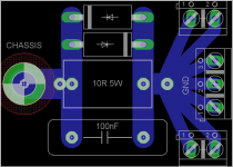
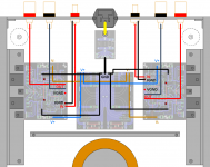
before starting to chassis work, i'm trying to finalize chassis layout and grounding scheme..
so my question is;
the 10R between signal and power ground is confusing me,
should i connect both IGND and VGND on the amp board to the star point? or this layout is quiet fine?
also i made a loop breaker board and set the star point onto the board.. board will be secured directly to the chassis screw..
what is your opinion and suggestions?
thanks in advance..
edit: diodes on the lb circuit are 1N5408, are they enough for the purpose?
for a while, i'm building a SymAsym amplifier.
http://www.lf-pro.net/mbittner/Sym5_Webpage/Images/Symasym5_2_eagle.GIF
before starting to chassis work, i'm trying to finalize chassis layout and grounding scheme..
so my question is;
the 10R between signal and power ground is confusing me,
should i connect both IGND and VGND on the amp board to the star point? or this layout is quiet fine?
also i made a loop breaker board and set the star point onto the board.. board will be secured directly to the chassis screw..
what is your opinion and suggestions?
thanks in advance..
edit: diodes on the lb circuit are 1N5408, are they enough for the purpose?
Attachments
Last edited:
monoblocks are so mcuh easier to gnd "right"
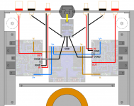
each channel's output and output gnd return should be twisted pair terminating on each channel board; no reason to make big loops with the loudspeaker load return current going to the PS before getting back to the boards
if your pic really shows the amp boards then my condolences – shows the classic poor layout with +,- power entering at opposite edges of the board
this makes it hard to do a proper low loop area PS, pwr gnd return – so you will have the half-wave rectified Class B currents possibly creating nonlinear magnetic coupling distortion
twisting PS gnd return with each of the +,- PS leads, you would have to hack the amp board to connect each PS gnd to near the respective on-board PS cap “gnd” side
the on board PS C are big enough that this may not matter as much as just getting very low Z amp board to PS gnd connection
since you don't show a volume pot there may be signal gnd options - is this driven from a low output Z preamp?
Last edited:
Hi jcx, thanks..
moved speaker gnds to the amp boards as your suggestions..
but i'm not sure, if i understood correctly what you mean..
moved +, gnd, - connections to the underside of the caps.. does this solve the problem?
by the way pcb is from the original design from the Michael Bittner,
http://www.lf-pro.net/mbittner/Sym5_Webpage/Images/symasym5_board_preview.GIF
and as far as i know, so many people built this amp with no problem..
i'm planning to use just a 22K pot which is what MikeB suggested.. but i'm planning to put it in a dac enclosure..
thanks..
moved speaker gnds to the amp boards as your suggestions..
twisting PS gnd return with each of the +,- PS leads, you would have to hack the amp board to connect each PS gnd to near the respective on-board PS cap “gnd” side the on board PS C are big enough that this may not matter as much as just getting very low Z amp board to PS gnd connection
but i'm not sure, if i understood correctly what you mean..
moved +, gnd, - connections to the underside of the caps.. does this solve the problem?
by the way pcb is from the original design from the Michael Bittner,
http://www.lf-pro.net/mbittner/Sym5_Webpage/Images/symasym5_board_preview.GIF
and as far as i know, so many people built this amp with no problem..
since you don't show a volume pot there may be signal gnd options - is this driven from a low output Z preamp?
i'm planning to use just a 22K pot which is what MikeB suggested.. but i'm planning to put it in a dac enclosure..
thanks..
Attachments
Last edited:
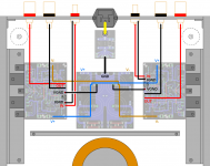
I was suggesting the extra pwr gnd wires to the amp board on-board 1000u caps - like the "hot fix" on-board amp pwr gnd jumper this could reduce some THD in careful measurements - may not make a big "sound" difference
the holes in the middle of the PS board gnd are fine on that end
any chance you would be willing to make a “Ground Canceling” buffer/driver in the DAC after the volume pot ( shown in Doug Self's books)
you should really have some sort of buffer after the volume pot - the high Z of the pot wiper will make the signal susceptible to noise pickup and will give varying fequency response with longer cables
a system may be acceptable with compromises vs “best” practice – sometimes you just have to try it and see what works in your system – decide if the “next level” is too inconvenient or expensive
Last edited:
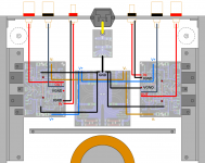
Signal grounds should go to their individual channels ground where they are disconnected by the 10 ohm resistor.
The speaker grounds should go to the GND of your power supply board. So should the VGND's from the amp boards.
Then, run one wire from the power supply board's GND terminal, to chassis ground, via your loop breaker. You may not even need the loop breaker. Try it without, and if you get hum when you connect a source to your amp, add it.
Make sure the grounds on your signal input sockets are isolated from the chassis. Make sure the ground on the IEC connector connects *directly* to your chassis - use a toothed washer to ensure grip.
i think, understood finally ")
but i should split to long jumpers because they are already on the top layer..
i'll search for a ground canceling buffer but my knowledge may limits me to choose a suitable one.. would you suggest me a specific circuit?
thanks for your helps..
but i should split to long jumpers because they are already on the top layer..
i'll search for a ground canceling buffer but my knowledge may limits me to choose a suitable one.. would you suggest me a specific circuit?
thanks for your helps..
Attachments
Self's web page: Balanced Line Technology shows a ground canceling circuit and lots more balanced line circuits, you do need a buffer between the volume pot and the divider resistors in most of those circuits
the ground canceling circuit should work OK with RCA, cold=shield - bypassing the gnd R at both ends with some C reduces the chance tht RF could be a problem - or could used shielded twisted pair XLR with "single ended" signal for higher RF immunity
could be done with your own op amps of choice, matched R or as an integrated example the INA111 is a possible instrumentation amp probably OK for audio
Last edited:
- Status
- This old topic is closed. If you want to reopen this topic, contact a moderator using the "Report Post" button.
- Home
- Amplifiers
- Solid State
- Grounding scheme and loop breaker, need advice..