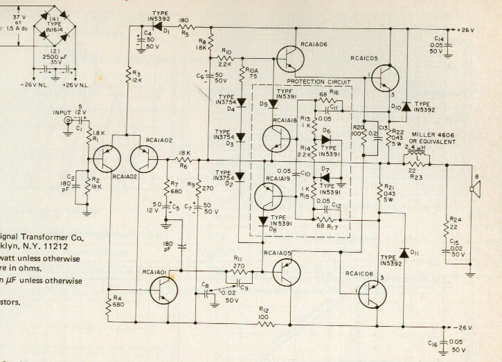
R1 is too high, not enough damping. Try 1r0 to 10r instead of 22r.
R11 is a variable resistor. Try 500r or 1000r
R13 is too small, try 100r to 220r.
RF attenuating resistor is missing. Try 1k in series with input cap C1.
The other half of the input signal connects to the bottom of C2, bottom of R2, bottom of C4, top of R9.
Add a trimmer to R14. This sets the currents through R5 & R4 exactly equal.
Then, adjust either R2 or R16 to set the output offset to zero mVdc.
Otherwise a good circuit to learn how an amplifier works.
Thanks for the advice Andrew.Ι had in mind AKSA and a RCA amplifier design of 1970 when designing this schematic.Thats why the lack of RF attenuating resistor at the input and the hi value of R1 which indeed is quite high.R11 and R13 where used in LTspice to find the optimum quiscent current.They will be replaced by a trimmer.I have not included resistors at the bases of drivers and output transistors and i think i should. My aim is to build an amp not with an ultra low distortion and flat sound,but one with warm sound.
Last edited:
Member
Joined 2009
Paid Member
Thanks for the advice Andrew.Ι had in mind AKSA and a RCA amplifier design of 1970 when designing this schematic.
Good choice ! ... but adding the rf filter is still a good idea for using the amp in a modern environment.
see also: http://www.diyaudio.com/forums/solid-state/145306-rca-1972-basic-amplifier-mods.html
By the way what happened to Ostripper's site? http://67.248.209.21/D:/WEBSITE/
There were many good amplifier schematics and their simulation files there.
There were many good amplifier schematics and their simulation files there.
You can do way better than that old RCA circuit. I built one back in the '70s as my first amp project. It worked well, but we've moved on! Here's a circuit I did some time ago using similar devices to what you have, based on the circuits and ideas in Doug Self's book. The circuit will do sub 0.001% THD over most of the audio range and is generally well behaved. The grounds were drawn the way they were so I could experiment with what to tie where. LCG stands for low current ground, HGC for high current ground. You can eliminate the opamp on the front end if you have no need for differential inputs. C12 is probably a bit heavy, so reduce it for better bandwidth and less filtering. Transistor types are not terribly fussy. There is no protection, so don't short it out! It should make a great headphone or small speaker amp.
Attachments
Last edited:
The circuit works as well with single pole compensation but I figured what the heck, let's try it. It wasn't all that troublesome and it did improve performance slightly. Warm, cold, sterile, accurate, tight , loose, I dunno, but the signals that come out exactly match the signals that went in.
I want to ask something.There many darlington pairs out there whether they are in a single package or made descrete. How we choose the values of these 2 resistors (R1-R2) when it comes to power amps? They have different values in many datasheets even if they are of the same model but different brand.

Last edited:
use discrete transistors and choose the resistors to get good performance from each transistor.
Too high a value of R2 reduces the driver transistor current to below it's optimum and the Ft falls off the cliff. Go to an even higher resistor value and the hFE then falls off the cliff.
That's the basic problem of the integrated Darlingtons. They are there to reduce production costs and only work well over a very small range of Ic value. That optimum Ic value rarely suits Audio Power Amplifiers.
Go discrete.
But (there's always a but), you can still build a very good and simple power amp with darlingtons. Find Motorola app note AN-483B, 15-60 Watt Amplifiers using Complimentary Darlington Transistors and try the final circuit. (I have it somewhere if you can't find it on-line) They give a design table for different power levels and the parts aren't all that critical. I've run one of these for decades as part of my tri-amped system. Long ago I did have an Integral Systems 100W/ch amp that used a simple pair of darlingtons on each channel. It had no protection circuitry and wasn't known for reliability, but I had no trouble with it. For the lower power considered here, the darlington approach has some merit, though still nowhere near as good spec-wise as the discrete circuit I posted. Question- do you think the RCA and other simple circuits have any advantage over a decent chip amp, say 3886? I ask that in all seriousness and don't have any answer or preconceived notions.
I found the application note but it is in spanish language. I have built two channels with LM3886 based on an Elektor circuit. Comparing it to a descrete amp i built 2 years ago based on RCA and other simple circuits i must admitt that the sound colors have more ''life'' than LM3886. NMOS200 and P3A sound better than LM3886 as well. LM3886 has a ''plastic and flat'' sound.


Last edited:
Member
Joined 2009
Paid Member
You can do way better than that old RCA circuit. I built one back in the '70s as my first amp project. It worked well, but we've moved on!
For sure, modern designs measure better and sound cleaner and more dynamic.
I haven't built many SS amps, but of those that I did, the one that still graces my desktop is the one based on the RCA schematic. It just sounds so nice. Sure it's not a higher performance amp. But I never tire of the sound, I find much to enjoy and little to criticize. It's fund to build, not difficult to debug and tune. It's just about my favourite.
Maouna, that schematic shows the simple diff front end everybody has used forever. Just adding the current mirror and extra resistors as I showed, even if you change nothing else, will improve the amp greatly. I can't tell from the picture but I think they wound the output inductor around a resistor. It's best not to do that!
As for the RCA circuit, yes I can't really fault it in terms of sounding nice and being a good place to start, but I just can't leave well enough alone!
As for the RCA circuit, yes I can't really fault it in terms of sounding nice and being a good place to start, but I just can't leave well enough alone!
Last edited:
- Status
- This old topic is closed. If you want to reopen this topic, contact a moderator using the "Report Post" button.
- Home
- Amplifiers
- Solid State
- 2 x 15W rms Audio Amp for small speakers