Current or not ...current....
Hi
Yes it is indeed a current fedback design!!
For another example of this tecnology see:
http://210.166.208.10/photo/e-530_e.pdf
The point here is that current feedback means that the sampled output voltage is injected in current form in the input stage that has very low impedance...
Some people here are confusing with feedback of current where a sample of output current is injected in the input stage...
In the former case the output impedance become small...in the second case the output impedance increase (it become a current generator)...
Regards
Well Jorge and others, nice story about the feedback signal injected as a current in the input stage, except that this doesn't make it CF. Voltage feedback means you feed back a sample of the output VOLTAGE (as in this Elektor amp). CF is when you feed back a sample of the output CURRENT.
Look at these circuits:
Fig a shows output voltage from output stage fed back by R and C - BY DEFINITION voltage feedback, even if it goes to the cathode of the first stage (functionally equivalent to the elector buffer output stage emitters), which is a low impedance, so one could indeed argue that the feedback signal is injected into the input stage as current. The point is that the feedback signal is proportional to the output voltage, thus VF...
Fig b : the output current develops a voltage across Rf, that signal is send back: the feedback signal is proportional to the output current, this is BY DEFINITION CF, even if it is fed back to a voltage-input (hi impedance, the grid).
Fig c: Clearly voltage feedback.
Fig d: Both VF from the output signal, and CF from the output current. The unbypassed Rk develops a voltage from tube's current (Ia = Ik) this current gives a voltage across Rk which is put in series with input voltage Es, but in opposite phase (after all, it IS negative feedback).
Fig e: This is the quiz. VF or CF?
Jan Didden
Attachments
Re: Current or not ...current....
Interresting, so you mean that all BJT (current controlled device)designs using a diff amp input is using current feedback, and FET (voltage controlled device) designs are voltage feedback?
\Jens
Tube_Dude said:
The point here is that current feedback means that the sampled output voltage is injected in current form in the input stage that has very low impedance...
Interresting, so you mean that all BJT (current controlled device)designs using a diff amp input is using current feedback, and FET (voltage controlled device) designs are voltage feedback?
\Jens
janneman: If I get you right then a sample of load current fed back constitutes CF, and the same with voltage and VF, irrespective of the impedance at the NI input.
If you are right then there are 2 problems for which I can only theorize a vague explanation. First problem is how to explain CF op-amps. Seems to me by your definition that they might not exist... and yet they exhibit certain blatant enhancements in performance consistent with CF.
The second problem I have stems from the first. What happens when you use a CF op-amp in inverting mode? The FB is then going to the high impedance input. Is this still CF?
I wonder if the definition of CF is not multifaceted... is the classical definition applicable to the Elektor circuit? Is it valid for CF op-amps? If it is simply that Vout~I(inv) for CF amps, then all can be explained easily. And then the design is indeed CF....
DrG said:janneman: If I get you right then a sample of load current fed back constitutes CF, and the same with voltage and VF, irrespective of the impedance at the NI input.
If you are right then there are 2 problems for which I can only theorize a vague explanation. First problem is how to explain CF op-amps. Seems to me by your definition that they might not exist... and yet they exhibit certain blatant enhancements in performance consistent with CF.
The second problem I have stems from the first. What happens when you use a CF op-amp in inverting mode? The FB is then going to the high impedance input. Is this still CF?
I wonder if the definition of CF is not multifaceted... is the classical definition applicable to the Elektor circuit? Is it valid for CF op-amps? If it is simply that Vout~I(inv) for CF amps, then all can be explained easily. And then the design is indeed CF....
I know, CF opamps DO exist. But that is a marketing term, that has confused a long standing understanding and definition of CF and VF. The diagrams I posted are from Engineering Electronics, by John D Ryder, Dean of Engineering and Professor of Electrical Engineering at Michigan State University. Published in 1957. (I have later references, but they are in Dutch...)
The blatant improvements in CF you mention are not at all due to CF! They are due to the fact that the feedback node is low impedance. The effect is present in both CF and VF amps, PROVIDED the feedback node is low impedance. Again, if you were in marketing, and your application guru came rushing to tell you he had invented an opamp with a Low Input Impedance Inverting Input, allowing you to feedback current into this low impedance node and giving it very good specs, how would you describe it in the brochure? A LIIIIA or a CFA?
Your second problem actually isn't one. It is the EXTERNAL CIRCUIT that determines whether a circuit is CF or VF. An opamp is just that, and in and of itself cannot be VF or CF. Only when you put in an external FB network you make it into a CF or VF circuit. (Opamps have internal feedback, actually ALL opamps have internal CF because of the degenerated emitter circuits and current sources. But as a black box amplifier they become alive for us users only with an external feedback circuitry).
Jan Didden
Re: Current or not ...current....
The point here is that you take the liberty to re-define the definition for CF and VF. Like saying: "the point here is that 1 kilometer is 456,7 yards".
And, how would you then call a circuit where the output CURRENT sample is injected in a low impedance node?
Better yet, how about a sample of the output current being injected into a high impedance node?
Jan Didden
Tube_Dude said:Hi
[snip]The point here is that current feedback means that the sampled output voltage is injected in current form in the input stage that has very low impedance...[snip]Regards
The point here is that you take the liberty to re-define the definition for CF and VF. Like saying: "the point here is that 1 kilometer is 456,7 yards".
And, how would you then call a circuit where the output CURRENT sample is injected in a low impedance node?
Better yet, how about a sample of the output current being injected into a high impedance node?
Jan Didden
Re: Re: Current or not ...current....
There is indeed four types of feedback circuits. My professor had different names and different symbols (Z,G,H...?) for each. I only remember their general differences:
1. Voltage output sensing creates voltage error signal
2. Voltage output sensing creates current error signal
3. Current output sensing creates voltage error signal
4. Current output sensing creates current error signal
For audio we usually only talk about types 1 and 2. For type-1 we use a VFB op-amp and for type-2 a CFB op-amp. That is why the op-amp manufacturers offers two types of op-amps.
Type 3 and 4 are essentially current-sources with high output resistance and not often used in audio. You can make type 1 and 3 with a VFB op-amp and you can make type 2 and 4 with a CFB op-amp.
Jan is different. If I understand him right, he is calling types 1 and 2 for VFB and types 3 and 4 for CFB independent of which op-amp is used, so his semantics differs from the rest of the world's... It doesn't really matter who is "right", but the rest of the world has come up with a de-facto standard, or marketing term as Jan calls it, and I recomend we stick to it to avoid further confusion.
janneman said:
And, how would you then call a circuit where the output CURRENT sample is injected in a low impedance node?
Better yet, how about a sample of the output current being injected into a high impedance node?
There is indeed four types of feedback circuits. My professor had different names and different symbols (Z,G,H...?) for each. I only remember their general differences:
1. Voltage output sensing creates voltage error signal
2. Voltage output sensing creates current error signal
3. Current output sensing creates voltage error signal
4. Current output sensing creates current error signal
For audio we usually only talk about types 1 and 2. For type-1 we use a VFB op-amp and for type-2 a CFB op-amp. That is why the op-amp manufacturers offers two types of op-amps.
Type 3 and 4 are essentially current-sources with high output resistance and not often used in audio. You can make type 1 and 3 with a VFB op-amp and you can make type 2 and 4 with a CFB op-amp.
Jan is different. If I understand him right, he is calling types 1 and 2 for VFB and types 3 and 4 for CFB independent of which op-amp is used, so his semantics differs from the rest of the world's... It doesn't really matter who is "right", but the rest of the world has come up with a de-facto standard, or marketing term as Jan calls it, and I recomend we stick to it to avoid further confusion.
ojg:
DrG:Jan is different... so his semantics differs from the rest of the world's... but the rest of the world has come up with a de-facto standard, or marketing term as Jan calls it, and I recomend we stick to it to avoid further confusion.
Seems my suspicion was on the money, albeit without the technical explanation. Thanks for clearing that up, ojg.I wonder if the definition of CF is not multifaceted...
janneman:
i) If the node into which this is fed is high-Z, then we are dealing with an error voltage - ie type 1 FB circuit listed by ojg.
ii) If the node is low-Z, then an error current is generated - ie type 2.
At no time is the CFB/VFB "mode" of operation determined by the external circuitry comprising the FB loop.
I know of one exception though, the Alexander amp. This uses a conventional VFB op-amp (SSM2131) as a CFB device by taking output from the power pins via current-mirrors, and feeding back amp signal into the op-amp output, which is a low-Z node...
This is not correct. The external FB circuit only feeds back a portion of the output signal:-It is the EXTERNAL CIRCUIT that determines whether a circuit is CF or VF.
i) If the node into which this is fed is high-Z, then we are dealing with an error voltage - ie type 1 FB circuit listed by ojg.
ii) If the node is low-Z, then an error current is generated - ie type 2.
At no time is the CFB/VFB "mode" of operation determined by the external circuitry comprising the FB loop.
I know of one exception though, the Alexander amp. This uses a conventional VFB op-amp (SSM2131) as a CFB device by taking output from the power pins via current-mirrors, and feeding back amp signal into the op-amp output, which is a low-Z node...
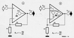
AMT-freak said:Picture is taken from an Elektor article about their high power amplifier. (a) is conventional, (b) is what they and what I call CFB, as implemented in the schematic from the first post and all current Accuphase gear.
AMT,
This is a nice picture of two VF amplifier circuits, one with a high impedance inverting input, the other with a low-Z ni input. Sorry. That's the decades-old definition. I cannot be made responsible for marketing ploys and ignorance of magazine editors.
Jan Didden
DrG/ojg,
The error voltage is the difference between input voltage and the feedback voltage, and as I'm sure you know, this error voltage is amplified by the open loop gain to drive the error towards zero. So, depending on how the comparison is made in the input stage, you can have eror voltage or error current.
The point we are discussing here is that when we feed back a sample of the output voltage, we have VF, if we feed back a part of the output current, we have CF.
Since the creation of the CFB opamp, many people who hadn't ever had a clue about the different types of feedback, or about feedback itself for that matter, began to parrot the CFB promotions (and these amps are very usefull, sure). But in schools and colleges around the world, what is tought is what I stated above. I didn't make this up!
So, again, marketing hijacked a perfectly good technical definition and everybody fell for it. It's like reading that the "LT 1234 wide band analog amplifier is now sampling" . Of course it is not sampling! It's an analog amp, for crissake. What they mean is that you can buy samples. Sloppy language, born from a lazyness to express correctly what we mean because it would cost a few more words. Once you study the most frequent causes of aircraft accidents, you would probably get very carefull with expressing yourself. Sorry, I get carried away.
So, I will continue to describe the Elektor amp as a VF amp.
Jan Didden
Jens the mind-reader
Jens,
I 100% totally and completely agree with you!
One remark: when you say, the oamp works to make the two inputs equal, that is equivalent to saying that the opamp has (ideally) infinite gain. Because of this, any small difference between the input voltages will immediately increase the output voltage until, via the feedback network, the two input voltages are again (almost) equal. Just a different way of saying it.
Jan Didden
I beg to differ
Firstly let me quote ojg:
The Elektor is a voltage amplifier where a sample of the output voltage used to generate an error current. Which is CFB to my mind.
Firstly let me quote ojg:
Now we all know version 1, so let's put it aside for the moment. And configurations 3 and 4 are also irrelevant because both must be transconductance amps of some kind. Which brings me to your .zip file, Jens. You define your hypothetical CFB amp to have a transfer function T as follows, and I quote:1. Voltage output sensing creates voltage error signal
2. Voltage output sensing creates current error signal
3. Current output sensing creates voltage error signal
4. Current output sensing creates current error signal
This is the transfer function of a transconductance stage to the best of my knowledge, which would also put the load inside the FB loop. Clearly this Elektor circuit is not of this type.T=Iout/Vin
I agree with this in principle but in ojg's scheme the circuit you have drawn is type 3 and not relevant to this Elektor amp.From this we see that the output current is independent of the load resistor RL. The feedback signal is a voltage, but the system generates an output current!
The Elektor is a voltage amplifier where a sample of the output voltage used to generate an error current. Which is CFB to my mind.
I disagree. The FB signal may be represented as voltage (VFB) or current (CFB) to the input stage, depending on circuit topology. This goes for FB in both voltage and transconductance stages.The terms Voltage feedback and Current feedback are related to the output of the system, and not the way the feedback signal is represented (voltage or current)
Jan,
I think you may be using VF and CF to define what is actually termed shunt and series feedback at the output respectively.
When you sample the output voltage of an amplifier you have shunt feedback at the output and when you sample the output current you have series feedback at the output.
These can be combined with series or shunt configurations at the input. So there are four types of amplifier feedback configurations,
series-shunt, voltage amplifier - A = Vo/Vi The most common.
shunt-series, current amplifier - A = Io/Ii
series-series, Transconductance - Gm = Io/Vi
shunt-shunt, Transresistance - Rm = Vo/Ii
I think the VF and CF refer to two different input stage configurations. With VF the signal returned to the input stage is infact a voltage which is some fraction of the output voltage/current. With CF the feedback signal is a current which is proportional to the output voltage/current.
The two configurations have different characteristics I think the most well known is the behaviour of the gain-bandwidth product.
By the way a diff pair in a voltage feedback amp does produce a current error signal but accepts a voltage as the fedback signal from the output.
Hope this clarifies things.
Dave
Feedback
Hi,
My point had nothing to do with the elektor VF amp.
Snip
Clearly this Elektor circuit is not of this type.
Snip
Nope you are right, it's not")
Snip
This is the transfer function of a transconductance
Snip
right again, but still CF
Snip
I disagree. The FB signal may be represented as voltage (VFB) or current (CFB) to the input stage, depending on circuit topology.
Snip
Well it all depends how the signal is put into the negative input (As Dave writes)
The terms SERIES and SHUNT are related to the input of the curcuit.
A way to determin what kind of FB is present is the folowing:
VF does not work when the output is shorted to ground
CF does not work when the output is unloaded
SERIES does nothing when the input is open or current controlled
SHUNT does nothing when the input is shorted to ground or is voltage controlled
\Jens
Hi,
My point had nothing to do with the elektor VF amp.
Snip
Clearly this Elektor circuit is not of this type.
Snip
Nope you are right, it's not
Snip
This is the transfer function of a transconductance
Snip
right again, but still CF
Snip
I disagree. The FB signal may be represented as voltage (VFB) or current (CFB) to the input stage, depending on circuit topology.
Snip
Well it all depends how the signal is put into the negative input (As Dave writes)
The terms SERIES and SHUNT are related to the input of the curcuit.
A way to determin what kind of FB is present is the folowing:
VF does not work when the output is shorted to ground
CF does not work when the output is unloaded
SERIES does nothing when the input is open or current controlled
SHUNT does nothing when the input is shorted to ground or is voltage controlled
\Jens
feedback terminology
I just did a little checking thru some books here, "Feedback" by Waldhauer (the Bible on feedback) and "Analysis and Design of Analog Integrated Circuits" by Grey and Meyer... (the Bible on Op Amps) and both appear to avoid the terms Current Feedback and Voltage Feedback. They do both use the same approach, but slightly different names for the four cases: (Waldhauer: SI = serial input, PI = parallel input, SO=serial output, PO = parallel output) (Meyer: series-shunt is series input, shunt output, shunt - series is shunt input, series output) So, the four cases (in = control signal input, observe = output, V=voltage, I=current):
A: SIPO = Series-Shunt -> Vobserve & Vin
B: SISO = Series-Series -> Iobserve & Vin
C: PIPO = Shunt-Shunt -> Vobserve & Iin
D: PISO = Shunt-Series -> Iobserve & Iin
(I don't think marketing will go for PISO op amps!)
Although their approach is unambiguous it is unfortunate that Series or Shunt means different things when refering to input or output as far as Voltage or Current goes. What a Mess!
I noticed that Horowitz uses VF and CF to refer to the actual feedback signal mode (ie input) and not the observed output mode. However, I think many older texts would refer to the observed mode. Probably why Waldhauer and Grey / Meyer avoid these terms. I will check "Feedback Amplifier Principles" by Rosenstark tomorrow (have on CD) and some other analog books to see how they handle this. You guys appear to have opened a can of worms here!
Don
Re: feedback terminology
Can of worms indeed! I have Sol Rosenstark's book in hardcopy (sneakily copied it in a Paris public library, of all places!), and I couldn't find an answer to the current issue.
Jan Didden
smoking-amp said:I just did a little checking thru some books here, "Feedback" by Waldhauer (the Bible on feedback) and "Analysis and Design of Analog Integrated Circuits" by Grey and Meyer... (the Bible on Op Amps) and both appear to avoid the terms Current Feedback and Voltage Feedback. They do both use the same approach, but slightly different names for the four cases: (Waldhauer: SI = serial input, PI = parallel input, SO=serial output, PO = parallel output) (Meyer: series-shunt is series input, shunt output, shunt - series is shunt input, series output) So, the four cases (in = control signal input, observe = output, V=voltage, I=current):
A: SIPO = Series-Shunt -> Vobserve & Vin
B: SISO = Series-Series -> Iobserve & Vin
C: PIPO = Shunt-Shunt -> Vobserve & Iin
D: PISO = Shunt-Series -> Iobserve & Iin
(I don't think marketing will go for PISO op amps!)
Although their approach is unambiguous it is unfortunate that Series or Shunt means different things when refering to input or output as far as Voltage or Current goes. What a Mess!
I noticed that Horowitz uses VF and CF to refer to the actual feedback signal mode (ie input) and not the observed output mode. However, I think many older texts would refer to the observed mode. Probably why Waldhauer and Grey / Meyer avoid these terms. I will check "Feedback Amplifier Principles" by Rosenstark tomorrow (have on CD) and some other analog books to see how they handle this. You guys appear to have opened a can of worms here!
Don
Can of worms indeed! I have Sol Rosenstark's book in hardcopy (sneakily copied it in a Paris public library, of all places!), and I couldn't find an answer to the current issue.
Jan Didden
- Status
- This old topic is closed. If you want to reopen this topic, contact a moderator using the "Report Post" button.
- Home
- Amplifiers
- Solid State
- Compact Power Amplifier from Elektor