Hello.
Basically I am clueless when it comes to the engineering of audio equipment.
My issue is that a speaker binding post (spade/banana combo) broke on my solid state amp. I opened the amp up to see what was going on in the inside.
What I found was that the speaker binding posts are attached to a PCB board.
My easiest solution to fix this is to unscrew the binding post from the PCB and replace it.
However, I am curious as what it would take to take the PCB out and create a PTP connection with the speaker binding posts?
The PCB is not connected to anything other than the binding posts and the L/R +/- wires.
It is a straight forward as taking the L/R +/- wires off the PCB and soldering them to direct to the speaker binding posts?
I apologize if this is an asinine question. I am truly interested in the answer but haven't been able to figure it out from searching.
Thanks so much!!
Regards.
In a word, yes. Just make sure you don't mix up the wires. Ensure the soldered joints are good, as significant current flows through them.It is a straight forward as taking the L/R +/- wires off the PCB and soldering them to direct to the speaker binding posts?
I just want to say thanks again for the help.
I ended up just replacing the OEM posts with some Pomona copper posts attached to the PCB as the amp came. It works and sounds good, possibly better than previous. Hard to say.
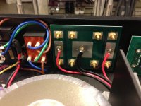
I am still interested in removing the PCB and going PTP, however, I couldn't figure out the negative wire channel setup. As the two negative wires are connected at the same point on the PCB. (see attached photo)
How do I determine which wire is for the L and R channels?
Again, I apologize if this is a elementary question. Electrical engineering has never been my niche (but I have lots of "face palm" stories.)
Thank you and best regards.
I ended up just replacing the OEM posts with some Pomona copper posts attached to the PCB as the amp came. It works and sounds good, possibly better than previous. Hard to say.
I am still interested in removing the PCB and going PTP, however, I couldn't figure out the negative wire channel setup. As the two negative wires are connected at the same point on the PCB. (see attached photo)
How do I determine which wire is for the L and R channels?
Again, I apologize if this is a elementary question. Electrical engineering has never been my niche (but I have lots of "face palm" stories.)
Thank you and best regards.
Attachments
- Status
- This old topic is closed. If you want to reopen this topic, contact a moderator using the "Report Post" button.