Welcome.
My first thread here.
About me: live in Poland, love vintage audio.
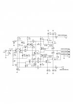
A power amplifier based on polish projects from 70ties. Simple, reliable, sounds very good, chip parts. In my project I used really "rubbish" elements, mostly from early 80ties but it works fine.
One can say it is nothing specjal, but this amp produce characteristic sound, something like old german Grundig amps.
It's RMS power is just about 25W sin for +-25V Ucc. THD about 0.1%.
My first thread here.
About me: live in Poland, love vintage audio.
A power amplifier based on polish projects from 70ties. Simple, reliable, sounds very good, chip parts. In my project I used really "rubbish" elements, mostly from early 80ties but it works fine.
One can say it is nothing specjal, but this amp produce characteristic sound, something like old german Grundig amps.
It's RMS power is just about 25W sin for +-25V Ucc. THD about 0.1%.
Attachments
")
It has one feature that isn't too common. R15, the biasing resistor, is boot-strapped from the feedback node (bottom of C3). This provides high input impedance while matching the DC values of the base resistors (R14=R15=3.3K).
That minimizes offset at the output due to bias current. That could otherwise be quite high on this design given the 3 mA tail current.
It seems a bit odd to have so large a value for C8...that dramatically decreases the miller feedback capacitance goodness. Perhaps it was needed for stability, but there might have been better ways to achieve that.
Akitika GT-101
Update My Dynaco
djoffe, you are right. Using such type of biasing was not common. The reason was a dramatic lack of good semiconductors in Poland. Originally polish electronic industry used obsolete BC157.
C8 too large? Ha! My prototype was dramaticly unstable, I tried to solve the problem. The problem is lack of the rc filter in the input stage, but R5 solve it. Actually there is no reason for such large capacity, works even without it.
Of course one can simplify this circuit removing T3, T4, D1, D2. Olso works fine without R1 and R2 ( more power).
Got enough time - try it, just for curiosity.
Sorry for my english!
Last edited:
Actually, R5 may have another mechanism to stability...If the input is open circuit, then the bootstrap connection provides positive feedback almost equal to the negative feedback, which would be quite bad for stability. The presence of R5 divides down the positive feedback thru the bootstrap path a bit, adding to the stability.
I wonder...should this amp also have a little bit of RF filtering on the front end? maybe 1k series and 100 pF shunt?
I wonder...should this amp also have a little bit of RF filtering on the front end? maybe 1k series and 100 pF shunt?
Member
Joined 2009
Paid Member
It has one feature that isn't too common. R15, the biasing resistor, is boot-strapped from the feedback node (bottom of C3). This provides high input impedance while matching the DC values of the base resistors (R14=R15=3.3K).
The input impedance is set by the shunt resistor R5. And an LTP usually has high enough input impedance without any bootstrapping. I don't see any need for the bootstrap except if the whole scheme was to allow low impedance feedback - afterall R14 is only 3k3 and without the bootstrap it should be sized to match R5.
djoffe:
This amp works properly and stable without RF filtering if it is conected by a pot 47k to a preamp. R5 is instead a pot, just for tests. But - RF filteringis should be used anyway.
Bigun :
See my prior post. This is a really ancient amp, construction from early 70ties, when polish production transistors were really bad, especially bad to use in low noise stages or differentail pairs. Such BC157 got the gain about 100 and were so noisy.... That times Poland was trully a poor country....
Amplifier works with no problems without R5 wen conected to a preamp via volume pot.
Using good transistors there is no need tu use such a bootstrap, but it is an "ancient" amp.
One can built more modern one, I love such oldies. Once I built modernized by Pavel Macura Sinclair's Z-30. Simply a "dinosaur", but sounds so sweet.....
Ian Finch :
I don't remember; about 30mA. I 'll measure it.
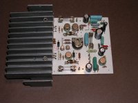
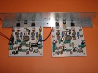
Here are photos of first "ancient" built for tests and a final wersion, still during tests.
There is a current source in the test version instead of a bootstrap.
Can't hear any difference in compartison to bootstrap.
Ian Finch : bias should be set from 20 to 30mA. I set 30mA for R21/R22 value 0.5 ohm. Works fine.
There is a current source in the test version instead of a bootstrap.
Can't hear any difference in compartison to bootstrap.
Ian Finch : bias should be set from 20 to 30mA. I set 30mA for R21/R22 value 0.5 ohm. Works fine.
Attachments
- Status
- This old topic is closed. If you want to reopen this topic, contact a moderator using the "Report Post" button.
- Home
- Amplifiers
- Solid State
- Another "ancient" amp