Elvee, we clearly both have been busy over the past month and work on this came to a hold on my side during that time. I'd like to proceed however and discuss an earlier design of yours: the same circuit using BJT's. Mind to take a look at some of the progress I made last week?
Don't expect design revolutions of some sort, I'm building on your earlier work.
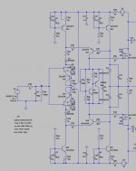
The attached design seems to be stable and fast, although I'm far from 500 V/uS. -3 dB bandwidth is approx. 3.5 mHz. With the 1K input potmeter turned all the way up that is. Input impedance could probably be improved, but is high enough for my application.
Not sure about how to further improve the design. Seems pretty good as it is right now, though it lacks a limiter for input voltage/clip warning and over current protection for the output transistors. I've seen some designs for all, but there seems to be quite some debate about it. Need to read more on that.
What bothers me most right now, is that I can't control the DC offset. Is there any way I can? Should I match on each side of the rail to minimise offset?
Anyway, I made some PCB designs, based on the Nmos350 layout. I borrowed Quasi's DC protection. Why this layout? I can't find complaints about it and it seems to meet general rules about PCB design. Moreover, it can be mounted on an 2U heatsink. Ccs transistors are coupled thermally by a 25 mm wide aluminium u-profile. Suggestions welcome as always!
Attachments
500V/µs is a nice figure, but it is not actually needed, and it would probably bring more problems than benefits.The attached design seems to be stable and fast, although I'm far from 500 V/uS. -3 dB bandwidth is approx. 3.5 mHz.
You seem to have arrived at a perfect tradeoff with 150V/µs, which should be ample enough
Since the clipping behavior is very clean, I don't think a limiter is required.Not sure about how to further improve the design. Seems pretty good as it is right now, though it lacks a limiter for input voltage/clip warning and over current protection for the output transistors. I've seen some designs for all, but there seems to be quite some debate about it. Need to read more on that.
A clip warning should be relatively easy to add, standard schemes should work here.
For the Circlophone, I have described such a circuit that could probably be adapted here.
You could add a protection, the topology allows it, but it is also a field where difficult choices are to be made: ensuring a completely bullet-proof protection without intruding into the normal operation of the amp is quite difficult.
Perhaps some form of latching protection: it is brutal, but at least it spares you the loop stability issues when the protection becomes active
The offset shouldn't be a problem in practice: it will be intrisically good thanks to the mock translinear loops formed by Q11,9,6,5 and Q8,10,12,13.What bothers me most right now, is that I can't control the DC offset. Is there any way I can? Should I match on each side of the rail to minimise offset?
All these transistors compensate each other and the vertical symetry provides a second layer of compensation, which means that even without any matching you will be under 10mV. Much less if you care to match them or use transistor arrays.
This looks like an excellent and robust designAnyway, I made some PCB designs, based on the Nmos350 layout. I borrowed Quasi's DC protection. Why this layout? I can't find complaints about it and it seems to meet general rules about PCB design. Moreover, it can be mounted on an 2U heatsink. Ccs transistors are coupled thermally by a 25 mm wide aluminium u-profile. Suggestions welcome as always!
Thanks for your patience and answers Elvee. Took me some time to reply due to busy schedules.
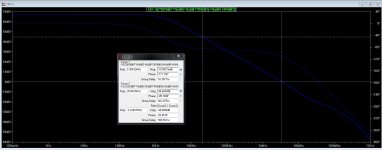
I noticed the slew rate is asymmetric. Is that normal? d(V(out)) shows the positive side being twice as fast as the negative side. Overshoot on larger signal swings confirms this.
I wrestled through most of the Circlophone topics entirely. I saw more clipping circuits; at the input and output, using zeners and/or ldr/leds. One of them seemed to compare input to output at the LTP. Not sure how that would apply in this buffer. Any leads of me on this?
About the DC offset again: if I insert a coupling cap between source and input of the buffer, DC offset is way of. I'm not sure yet if I want a high voltage coupling cap (can be safer if the source - a tube guitar amp at full power through a load - fails because of a faulty output transformer), but it seems good measure.
Design wise this seems like a go from your part. I intend to use a 2x35V PSU of 200VA with 10.000uF per side. Should be sufficient for 100 Watts if I'm not mistaken. Will maybe swap the BD139/140's for MJE340/350. Can't find Philips parts for a reasonable price even in Holland and the MJE's seem to work evenly well.
Since the circuit is completely symetrical, any difference between + and - behavior is entirely caused by different parameters of the P and N transistors chosen.I noticed the slew rate is asymmetric. Is that normal? d(V(out)) shows the positive side being twice as fast as the negative side. Overshoot on larger signal swings confirms this.
Some complementary pairs will be better than others in this respect, and low power/drivers pairs could be selected to have a behavior inverse of the OP.
The early warning part of this circuit could be used just for that: replace the optocoupler by a LED, adapt the resistor value to the desired brightness and the zeners to the degree of "earliness" you want.I wrestled through most of the Circlophone topics entirely. I saw more clipping circuits; at the input and output, using zeners and/or ldr/leds. One of them seemed to compare input to output at the LTP. Not sure how that would apply in this buffer. Any leads of me on this?
Here again, any offset current is caused by imperfect complementarity between transistors.About the DC offset again: if I insert a coupling cap between source and input of the buffer, DC offset is way of. I'm not sure yet if I want a high voltage coupling cap (can be safer if the source - a tube guitar amp at full power through a load - fails because of a faulty output transformer), but it seems good measure.
To minimize this effect, you could use a relatively low value of resistor to ground after the cap (and a large enough cap), but since your source is tranformer-coupled, there is no risk of DC level, even if the amp fails completely
Seems reasonableDesign wise this seems like a go from your part. I intend to use a 2x35V PSU of 200VA with 10.000uF per side. Should be sufficient for 100 Watts if I'm not mistaken. Will maybe swap the BD139/140's for MJE340/350. Can't find Philips parts for a reasonable price even in Holland and the MJE's seem to work evenly well.
That part about coupling is off course true for 99% of the cases of failure in a tube amp: no DC because of the output transformer. That's practically why it is there. Only case I could think of, is a short between the output primaries and secondaries. I know, it's rare and probably a fuse would immediately pop...
I'm going to work with your suggestions. Thanks again for your help!
I'm going to work with your suggestions. Thanks again for your help!
Hi Elvee,
It's been a long time since we last talked about buffers . I've got to admit: I didn't make much progress since March. The buffer I currently use leaves some features to wish for, but it's already pretty good (and simple!).
However, there is one thing that still annoys me: I'm still in need of a decent effects loop. Let me elaborate a bit about using effects with guitar (for those not familiar with it). Common practice is to use overdrives, distortions, wah-wah, etc. in front of the amp. Time based effects (chorus, verb, delay, etc.) go in the effects loop. The loop is after the guitar preamp en before the phase inverter (pretty common, but there are exceptions of course). Key is that the distorted sound gets delay or reverb and that the signal with delay or reverb doesn't distort any further. I've tried delay in front of the amp, but things tend to get messy and uncontrollable that way.
Now here's the first problem: I play flat out through a attenuator so the phase inverter and power tubes distort (mainly the PI). This means distortion after the effects loop. Seems like a bad idea to me...
Best idea seems to put the loop after the attenuator network but before the buffer amp. The buffer stays perfectly clean. Thing is: the output of the buffer is pretty high impedance (250k pot) which makes DC offset go to high with the afore discussed buffer. Thus I need something that either converts 250k output to 1k input impedance or ways to improve the input impedance of the buffer. Tried cathode and source followers after the buffer, but a 1k pot (which is ideal with this buffer) loads it down to much.
Any suggestions?
It's been a long time since we last talked about buffers
. I've got to admit: I didn't make much progress since March. The buffer I currently use leaves some features to wish for, but it's already pretty good (and simple!). However, there is one thing that still annoys me: I'm still in need of a decent effects loop. Let me elaborate a bit about using effects with guitar (for those not familiar with it). Common practice is to use overdrives, distortions, wah-wah, etc. in front of the amp. Time based effects (chorus, verb, delay, etc.) go in the effects loop. The loop is after the guitar preamp en before the phase inverter (pretty common, but there are exceptions of course). Key is that the distorted sound gets delay or reverb and that the signal with delay or reverb doesn't distort any further. I've tried delay in front of the amp, but things tend to get messy and uncontrollable that way.
Now here's the first problem: I play flat out through a attenuator so the phase inverter and power tubes distort (mainly the PI). This means distortion after the effects loop. Seems like a bad idea to me...
Best idea seems to put the loop after the attenuator network but before the buffer amp. The buffer stays perfectly clean. Thing is: the output of the buffer is pretty high impedance (250k pot) which makes DC offset go to high with the afore discussed buffer. Thus I need something that either converts 250k output to 1k input impedance or ways to improve the input impedance of the buffer. Tried cathode and source followers after the buffer, but a 1k pot (which is ideal with this buffer) loads it down to much.
Any suggestions?
Are you sure you mean the output of the buffer, not the input?Best idea seems to put the loop after the attenuator network but before the buffer amp. The buffer stays perfectly clean. Thing is: the output of the buffer is pretty high impedance (250k pot) which makes DC offset go to high with the afore discussed buffer.
Thus I need something that either converts 250k output to 1k input impedance or ways to improve the input impedance of the buffer. Tried cathode and source followers after the buffer, but a 1k pot (which is ideal with this buffer) loads it down to much.
Good buffers do exist, I have published one example in the Circlophone thread, but I am not sure I understand what you need.
Can you post a schematic of your current configuration, with the location where you intend to insert your reverb highlighted?
Are you sure you mean the output of the buffer, not the input?
Good buffers do exist, I have published one example in the Circlophone thread, but I am not sure I understand what you need.
Can you post a schematic of your current configuration, with the location where you intend to insert your reverb highlighted?
I meant the output of the effects loop is high impedance! Sorry being not so clear
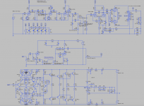
In the schematic I attach you can see my thoughts. Guitar amp --> load (12.5 Ohm resistor, coils and caps) --> effects loop (effects like reverb go in between 250k pots in the middle; jack connectors left out of the schematic) --> buffer amp (in this case your buffer Elvee).
This loop is tube based to reach high voltage levels. I want to process the full output swing of the guitar amp. Tried a very similar loop with simple jFets, but could only use half the rail voltage of the buffer. Thus I was out of headroom fast! However, using tubes only makes everything more complicated.
Tried to match the output impedance of the loop with the input of the buffer with source and cathode followers to no avail. Seems the buffer needs a 1k driving impedance at most, but 1k is a too big load for a cathode follower and its output voltage drops (CF has 1k3 output impedance).
It seems to me that at this point I might as well part from the buffer idea. The buffer was used to, well, buffer the voltage of the load mentioned before. The high output voltage of the load (around 30V RMS iirc) now becomes a handicap with the loop: only a tube effects loop can handle it (or using high voltage MOSFETs) and would require another power supply. And then there still is the low input impedance of the buffer.
Another solution I can think of is using a regular power amp instead of the buffer and knocking the signal down to line levels just after the load with a voltage divider. That wouldn't require a high voltage loop and I guess I could find an amp that is pretty simple (gain clone, class d module) with a high(er) input impedance.
However, those new ideas are seriously off topic here
I'd like to know your opinion about the feasibility of the first and latter option: is in your opinion the buffer option still the best solution given my loop wishes?
Attachments
Using commonly available, small tubes it is possible to obtain an output impedance <100 ohm without too much difficulty:
http://www.diyaudio.com/forums/tube...e-buffer-circuit-using-12au7.html#post3262203
That is probably the most suitable solution.
Another option would be to boost the supplies of a classical buffer (Dadod and others have described such high perf circuits), and use adequate transistors of course: BF470, BF471, MJE340, MJE350, etc
What is that tube Buffer called?
I can see that u2 is the Follower, but what is u1 doing?
I can see that u2 is the Follower, but what is u1 doing?
An answer back in the original Thread would be appropriate.Note that U2 works with a slightly positive bias; this is because the valves operate with less than 50V Vak, which is really short.
However, this is not detrimental to the performances since U2 operates in a quasi stasis mode (except maybe for the input impedance): the THD remains below 0.007%
Thanks for the suggestion Elvee! Much reading material for me, still got lots to learn.
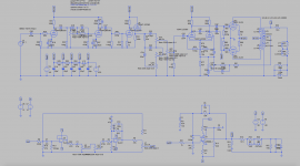
I also figured I could drive the buffer with a lower impedance source like a good opamp. The lower voltage swing (lower than the output voltage of the load of the guitar amp) would still be problematic. So to my limited knowledge there are 2 option: 1) convert to high(ish) voltage and make a tube loop and impedance matcher e.g., 2) lower the output voltage of the load with a voltage divider (essentially a fixed line out) and continue after that with regular opamps and a chipamp e.g.
Both solutions have got their advantages and disadvantages, but the more I think of it, the more logical it seems to got the second route. Effects don't need high voltage and I could even incorporate a built in reverb unit after the loop.
Once again, the second idea is 'slightly' off topic and polluting an otherwise clean buffer thread. Probably better to continue elsewhere on the forum and open a new thread.
Again thanks for all your help Elvee.
I also figured I could drive the buffer with a lower impedance source like a good opamp. The lower voltage swing (lower than the output voltage of the load of the guitar amp) would still be problematic. So to my limited knowledge there are 2 option: 1) convert to high(ish) voltage and make a tube loop and impedance matcher e.g., 2) lower the output voltage of the load with a voltage divider (essentially a fixed line out) and continue after that with regular opamps and a chipamp e.g.
Both solutions have got their advantages and disadvantages, but the more I think of it, the more logical it seems to got the second route. Effects don't need high voltage and I could even incorporate a built in reverb unit after the loop.
Once again, the second idea is 'slightly'
off topic and polluting an otherwise clean buffer thread. Probably better to continue elsewhere on the forum and open a new thread.Again thanks for all your help Elvee.
Attachments
That's probably the most sensible option. A very high performance and difficult circuit like this one has some aesthetic and intellectual attraction, but is it actually needed for such an application?Both solutions have got their advantages and disadvantages, but the more I think of it, the more logical it seems to got the second route. Effects don't need high voltage and I could even incorporate a built in reverb unit after the loop.
- Status
- This old topic is closed. If you want to reopen this topic, contact a moderator using the "Report Post" button.
- Home
- Amplifiers
- Solid State
- Alternative buffer topologies