Hello everyone,
I just finished my Leach Amp and performed some tests on my oscilloscope (analogic, 20MHz).
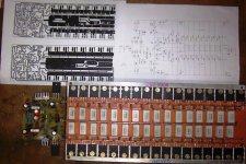
For the test, I used a DIY resistive load, as you can see in this picture:
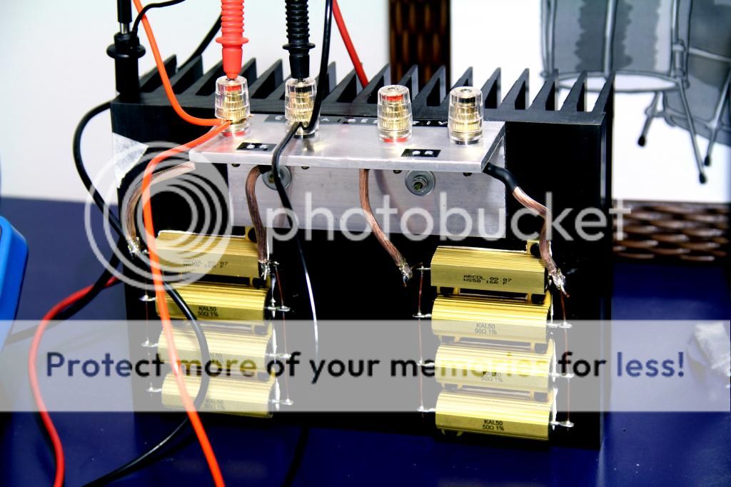
I have two 8 ohms arrays, which I can connect in parallel to get 4 ohms.
I injected a 1kHz sine wave to the input, and the output wave looks fine on the scope. Just before clipping, I measured 32V AC RMS at the output. The input signal was 1,5V peak.
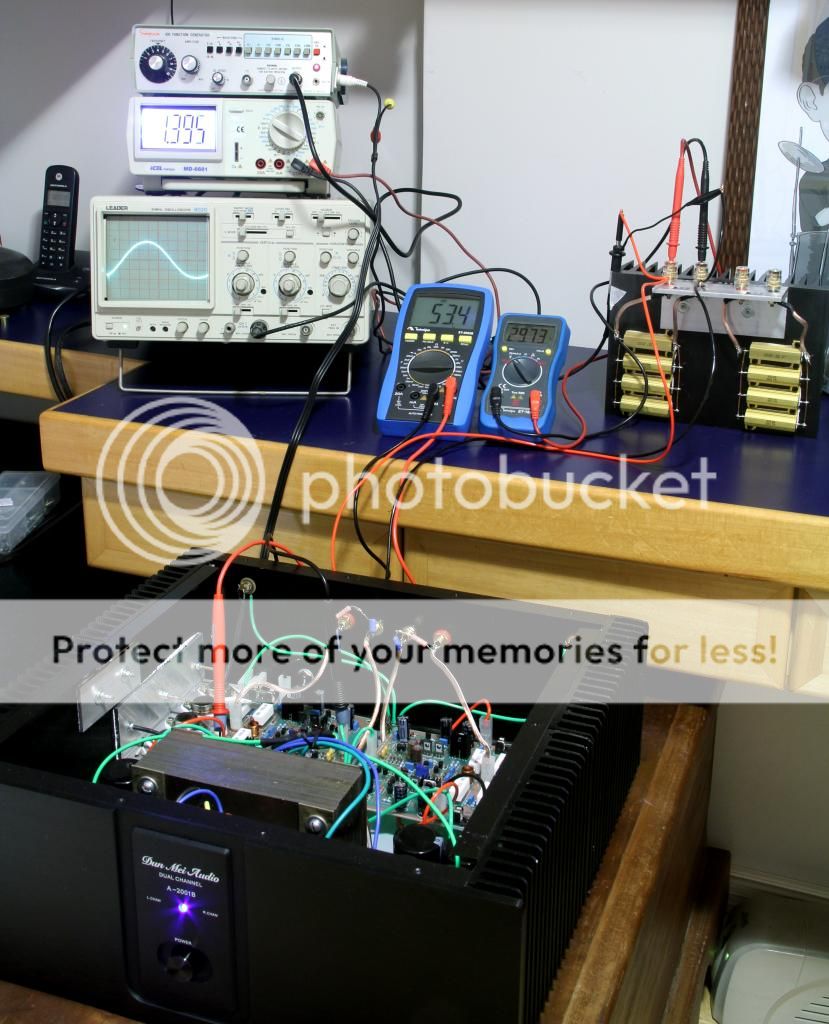
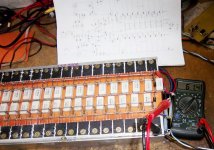
Here's a picture of the test: Above the scope, I have a multimeter set to measure the sine wave at the input (1.395V peak). Above this multimeter, I have the function generator. The other two hand multimeters (blue ones) are measuring the power supply positive voltage, and the other one is measuring the output voltage (this one is True RMS).
The power output measured just before clipping was:
128W RMS @ 8 ohms
225W RMS @ 4 ohms
At maximum output, the power supply voltage dropped from +/-58Vcc to +/-54Vcc (8R) and +/-50Vcc (4R).
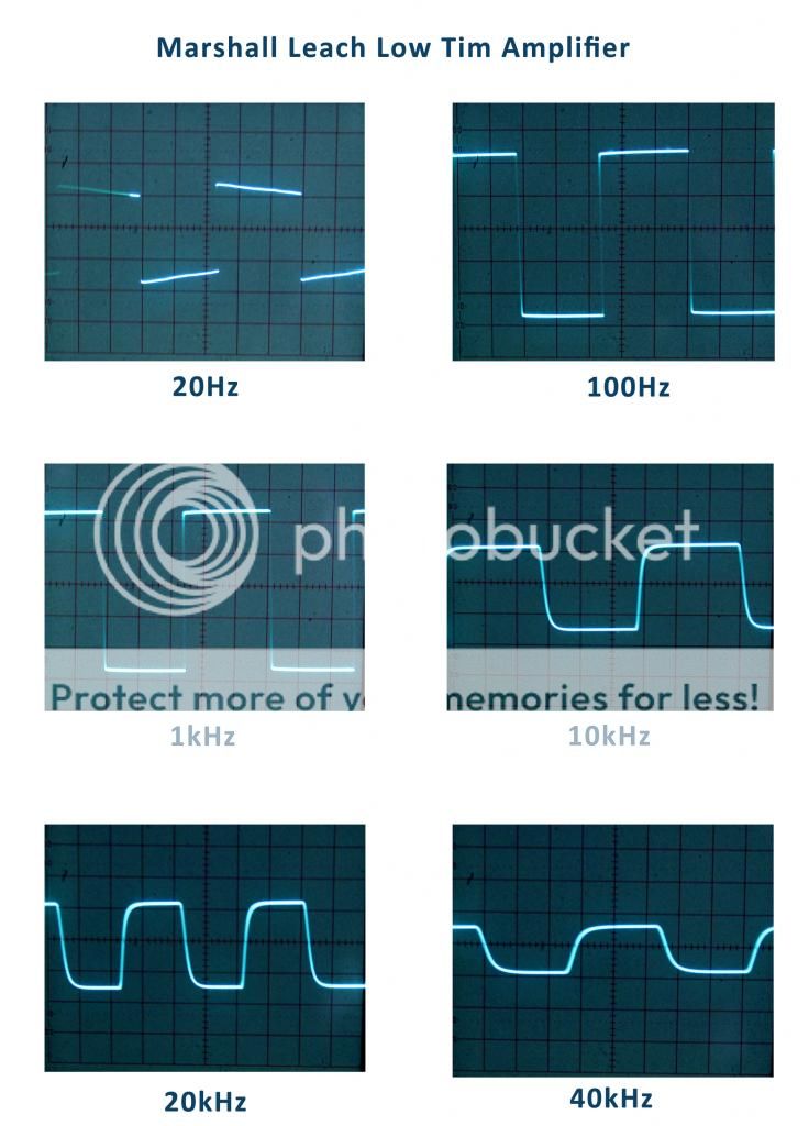
Then, I decided to inject some square waves, and this is the result:
There were two things that made me worried:
1) The output resistors (5W ceramic) got to 65ºC at maximum power output at 4 ohms.
2) There is a weird noise coming from the board. This noise varies according to the sine wave injected. It's just like there were a small loudspeaker reproducing the sine wave at the input. I can't figure out whether it's coming from the output inductor or the output transistors' case.
Can anyone help me with that?
Other than that, the amplifier sounds really good with my speakers!
I just finished my Leach Amp and performed some tests on my oscilloscope (analogic, 20MHz).
For the test, I used a DIY resistive load, as you can see in this picture:
I have two 8 ohms arrays, which I can connect in parallel to get 4 ohms.
I injected a 1kHz sine wave to the input, and the output wave looks fine on the scope. Just before clipping, I measured 32V AC RMS at the output. The input signal was 1,5V peak.
Here's a picture of the test: Above the scope, I have a multimeter set to measure the sine wave at the input (1.395V peak). Above this multimeter, I have the function generator. The other two hand multimeters (blue ones) are measuring the power supply positive voltage, and the other one is measuring the output voltage (this one is True RMS).
The power output measured just before clipping was:
128W RMS @ 8 ohms
225W RMS @ 4 ohms
At maximum output, the power supply voltage dropped from +/-58Vcc to +/-54Vcc (8R) and +/-50Vcc (4R).
Then, I decided to inject some square waves, and this is the result:
There were two things that made me worried:
1) The output resistors (5W ceramic) got to 65ºC at maximum power output at 4 ohms.
2) There is a weird noise coming from the board. This noise varies according to the sine wave injected. It's just like there were a small loudspeaker reproducing the sine wave at the input. I can't figure out whether it's coming from the output inductor or the output transistors' case.
Can anyone help me with that?
Other than that, the amplifier sounds really good with my speakers!
Last edited:
Continuing on then from where we left off 🙂
The noise is normal and could be either or both the transistors and inductor.
As to any resistors getting hot. 65c is ice cold for a ceramic so no worries there. Do remember though that testing at full power is a world away from normal "domestic levels". Also squarewave testing (particularly at full power and HF) can be a real killer so be careful.
I don't think you have anything to worry over 🙂
Update: about the noise - I injected music to the input, and I can hear it being plaid at a really low volume through the board (not sure if by the output inductor or TO3 case). Is this normal? I can only hear it beacause I'm using the resistive load. If I connected loudspeakers, I wouldn't be able to hear this noise, because it's too low.
Thank you Mooly! This amp is a true beast! It passed a tough test with resistive load and sine wave with ease!
Mooly said:As to any resistors getting hot. 65c is ice cold for a ceramic so no worries there
Good to know, Mooly! Thanks a lot!
Your welcome.
When I first encountered transistors "singing" I couldn't quite believe it but they do, particularly the TO3 style.
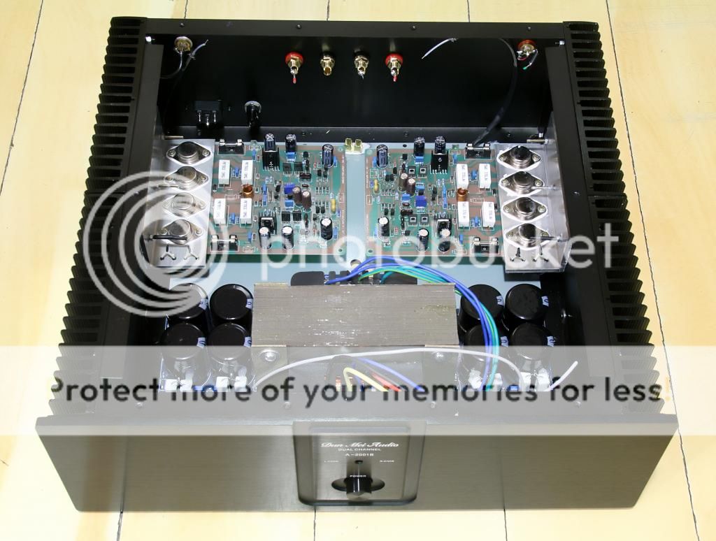
Nice job too 🙂 Can see it better now.
When I first encountered transistors "singing" I couldn't quite believe it but they do, particularly the TO3 style.
Nice job too 🙂 Can see it better now.
better results
For better results.
1. make the condensator c9 and c10 100pf.
2. leave out condensator c8.
ATOMIC
For better results.
1. make the condensator c9 and c10 100pf.
2. leave out condensator c8.
ATOMIC
This all sounds normal to me, I'm very familiar with the TO-3 "singing". Voltages and waveforms are what I would expect. Trimming bias for lowest distortion with an analyzer would be nice, but not essential; just keep a finger on the heatsinks to see how warm they get. You could increase the bias until the amplifier runs warm but not hot at idle, and that should result in lower crossover distortion, from my experience with the design.
EXCELLENT job on the chassis! Looks far nicer than my industrial monster.
EXCELLENT job on the chassis! Looks far nicer than my industrial monster.
you can mount the zobel networks on a small board directly mounted on the speaker jacks instead of on the board itself.......
Singing circuits 🙂
I've even had a goldplated spade terminal connected by a crockclip sing (this was output wire to dummy load).
Weird but fun, this was also when driving the amp into clipping during tests.
I've even had a goldplated spade terminal connected by a crockclip sing (this was output wire to dummy load).
Weird but fun, this was also when driving the amp into clipping during tests.
Boon of Dr. Marshal Leach
This circuit by Late.Dr .Leach is a boon
I made this extended version and got on2 ohm what meter is showing , and 47 volts with 8 nos.15" speakers connected directly that is 1 ohm for 6 hours, nice clear sound without distortion.. have tested it up to .5 ohms on dummy + speaker loads
This circuit by Late.Dr .Leach is a boon
I made this extended version and got on2 ohm what meter is showing , and 47 volts with 8 nos.15" speakers connected directly that is 1 ohm for 6 hours, nice clear sound without distortion.. have tested it up to .5 ohms on dummy + speaker loads
Attachments
- Status
- Not open for further replies.
- Home
- Amplifiers
- Solid State
- Leach Amp Tests (weird noise)