Hi Guys
A ringing amplifier output is aberrant behaviour, so measuring THD during such an incident is counterintuitive; I don't know of anyone making such a test. As to audibility, that will depend on the frequency of the ringing.
In some situations ringing will sound like a chirp or glitch. I've heard this and the scope verifies it.
As far as I know, the 2uF in parallel with 8R was suggested by a magazine reviewer as a way to mimic the loading of an amp by an electrostatic panel. It would be interesting to know what capacitance the raw panel looks like - it would be reflected differently to the amp as most ESLs have a drive transformer with a high step-up ratio around 75x or so. Maybe this puts the raw panel at 27nF-ish?
Otherwise, most amplifier ringing corresponds to quite high ultrasonic frequencies according to most intell. And counterintuitively it is loading in the 100nF range that can cause more difficulty than the 1-2uF range for many amps.
Have fun
Kevin O'Connor
Any time I have tested a solid state amp, excited with a square wave and loaded with a capacitive load, I see ringing on the square wave. That is, IF it has an output inductor. Beyond that, I know nothing.
I think the value for some ESLs have been stated in one of the ESL threads here. I can't recall at the moment. Undoubtedly the inductance of the transformer will have some effect, but perhaps not very much in the audio band, I am guessing.
I'm not talking about parasitics or other oscillations.
_-_-bear
PS. guess what i am aiming at is that an output inductor would appear to have an effect on the way a circuit deals with "fast" signals and things like impulses - like maybe a fast cymbal shot?
"I agree better vas transistors are available but at least they are much better than mje340/350 which are commonly still found even on commercial products."
These are terrible. Their parameters change a lot with Vce and in the VAS role they often lead to parasitic oscillation on the signal peaks - especially if driving mosfet outputs. They are load switching devices.
These are terrible. Their parameters change a lot with Vce and in the VAS role they often lead to parasitic oscillation on the signal peaks - especially if driving mosfet outputs. They are load switching devices.
Hi Guys
Every study ever cited about how fast music signals are concur that there is nothing that even approaches the steepness of a squarewave. I assume this includes things which to human perception are very fast, such as a cymbal crash, as that is a "natural" instrument sound as compared to an electronically generated signal.
Where squarewave testing is good for assessing certain aspects about the circuit performance, it does not look like ringing through the tiny inductor into a capacitive load means anything at all. I believe if you look at the amplifier side of the choke you will see a good wave and at the output the ringing. The rise time of the step is more critical to how much overshoot occurs, with faster waves causing greater overshoot.
The typical 40kHz or so ringing is just the resonance of the output inductor with the load and does not reflect a problem with the amp itself. oscillations within the amp are much higher -100-500kHz - and are usually destructive. Low-feedback designs have greater immunity to capacitive loading causing oscillation than do high-feedback designs.
In the LU buffer, the gain of importance is in the diamond feedback stage. The transconductance there can be "compromised" as I did in my "slow" version with bootstrapped resistive current sources for the front end. This tends to make the circuit more stable without an output inductor.
Have fun
Kevin O'Connor
Dunno about every study doing anything.
But my experience is that I can predict to some degree of certainty the general nature of the sound that an amplifier will produce when listened to by looking at the leading edge of a square wave output from the amp on a scope.
So, if you think that that little blip of overshoot is inaudible, or more precisely is not a predictor of the general sonic category of an amp, that's fine, it's not been my experience thus far. Of course, I may be delusional, and people have said worse, so feel free to join in should you be so moved.
_-_-bear
yes that overshoot, or the opposite, overly rounded, will impact on the sound when the signal is not a simple single tone.
It is a much under utilised technique for setting up an amplifier. JLH described it in at least one of his amplifier builds.
It is also used oppositely. Some builders use the deliberate overshoot emphasis to give "enhanced" treble bite & detail. Quite wrong in my view.
The problem with this "by ear" technique is that the builder usually does not realise/know what they are doing.
I think there are numerous reasons for ringing on an amp, and each may cause different effects. For example, some options:
Low damping on the LC output.
Slow recovery from slew rate limitng.
Low phase margin.
Single stage parasitic oscillation.
The first two would appear to only cause a problem if the excitation is fast enough, for example do the fastest audio transients actually cause slew rate limiting (or get reasonably close). In which case then yes the amp will show severe distortion (at least for insufficient slew rate).
I'm not sure how low phase margin would cause added distortion, I would expect it to simply be a reliability concern as aging or speaker substitution may cause it to become unstable.
Parasitic oscillation may or may not be heard (as it would depend on its envelope or the susecptibility of other stages within the amp to it) but should be measurable in some form (direct oscillation or increased offset, power etc).
THanks
-Antonio
Hi Guys
Unless the amplifier is poorly designed, oscillations from within the amplifier are usually high frequency, as above, so you won't hear them. if they do not destroy the amp, you will notice overheating of the amp, and if this is while listening to the amp, you might notice a graininess in the sound.
If the stability margin is eroding towards positive feedback, this sounds fatiguing and the sound will lack resolution.
The ringing referred to above is strictly the resonance of the output inductor with the reactive load. A properly designed amp will absorb reverse currents associated with this and not be damaged. As discussed in another thread, if you can hear what the output inductor does then its value is far too high.
The studies mentioned are the mass of independent reviews made by various investigators to determine how fast audio signals can be. These studies began even before the notion of TIM or slew rate limiting had such names. See external sources for links - Pass has a link to one study, for example. The rise times of music studied could be fast enough to warrant better OT design in tube days, but was never so fast as to cause a problem for properly designed BJT gear. First generation BJT amps were utter garbage; second generation was passable; third generation finally got it right.
Speed and bandwidth in an audio circuit has both benefits and perils. Every design is a compromise.
Have fun
Kevin O'Connor
...
If the stability margin is eroding towards positive feedback, this sounds fatiguing and the sound will lack resolution.
...
Kevin
Interesting, I dont understand why this would be so (unless its actually oscillating some of the time). Can you supply some comments or links as to the rationale?
Thanks
-Antonio
Hi Guys
I'm sure all the Nyquist and control theory math predicts this and explains it if you understand any of it. I don't, so have to rely on my own experience.
This is an effect that is easier to hear in preamp circuitry, where the is no risk of devastation. Poor layout is a key cause to positive feedback in this situation, but so can be the circuit design.
An example is the Dynaco phono preamp. This uses a combination of positive and negative feedback. The former tends to increase gain where the latter reduces it. In the context of a phono EQ, high frequencies are being rolled off anyway, so the circuit is generally stable. However, if you use a similar circuit for straight voltage gain, as you increase positive feedback from a point of transparent effect to where you can hear it, the sound is dry, raspy and fatiguing.
As long as the circuit is not going to destroy itself, I would think the audible effects would be the same for a large-signal circuit. As positive feedback is increased, the stability margin is being eroded until the circuit breaks into oscillation. At that point, Nyquist has left the building but you now have a stable oscillator.
Have fun
Kevin O'Connor
Last edited:
Kevin
Been busy preparing for the holidays (always hard to take time off work) but I still dont get the association with phase margin.
Seems to me that given a constant cross-over loop frequency, the only way to get less phase margin is to either increase the loop gain or move the dominant pole to a slightly higher frequency. Both of these should result in an overall increase in loop gain (gain bandwidth within 20Khz) and thus should lower distortion.
Happy holidays
-Antonio
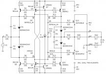
Scheme can be greatly simplified if we use the type transistors Lateral. Duple difkaskad FET input impedance stabilizes.
Using a third-wire and resistor R20 provides a small negative output resistance, which reduces the noise on the wires because Back EMF.
http://s55.radikal.ru/i149/1402/9f/e2d0182a132e.png
best regards
Petr
Using a third-wire and resistor R20 provides a small negative output resistance, which reduces the noise on the wires because Back EMF.
http://s55.radikal.ru/i149/1402/9f/e2d0182a132e.png
best regards
Petr
Get about the same effect as using the output transistors of one structure
http://s019.radikal.ru/i642/1402/0a/473666f87b01.png
best regards
Petr
http://s019.radikal.ru/i642/1402/0a/473666f87b01.png
best regards
Petr
Scheme can be greatly simplified if we use the type transistors Lateral. Duple difkaskad FET input impedance stabilizes.
Using a third-wire and resistor R20 provides a small negative output resistance, which reduces the noise on the wires because Back EMF.
http://s55.radikal.ru/i149/1402/9f/e2d0182a132e.png
best regards
Petr
Hi petr, would it be possible to make an input diamond that do not require biasing and input caps..??
Also the ZVN/ZVP are much more symmetrical parts than the IRFs..
MiiB (254)
Hi petr, would it be possible to make an input diamond that do not require biasing and input caps..??
Also the ZVN/ZVP are much more symmetrical parts than the IRFs..
Hello, MiiB!
This requires a powerful complementary transistors with logic level control and high transconductance as IRL2910, IRL640
But I do not know them complementary
best regards
Petr
Hi petr, would it be possible to make an input diamond that do not require biasing and input caps..??
Also the ZVN/ZVP are much more symmetrical parts than the IRFs..
Hello, MiiB!
This requires a powerful complementary transistors with logic level control and high transconductance as IRL2910, IRL640
But I do not know them complementary
best regards
Petr
Scheme can be greatly simplified if we use the type transistors Lateral. Duple difkaskad FET input impedance stabilizes.
Using a third-wire and resistor R20 provides a small negative output resistance, which reduces the noise on the wires because Back EMF.
http://s55.radikal.ru/i149/1402/9f/e2d0182a132e.png
best regards
Petr
Hi Pertr,
Can you reload the images?
Thanks!
Edward
Here is the error correction output buffer
Thanks!
So it is based on two MOSFET differential pairs.
"Here is the error correction output buffer "
I would suggest 1N4148 type diodes in series with each of the zener diodes.
The zener diodes have a non-linear capacitance with the audio voltage. The added diodes will allow this capacitance to charge up, but not discharge into the gates during normal operation.
I would suggest 1N4148 type diodes in series with each of the zener diodes.
The zener diodes have a non-linear capacitance with the audio voltage. The added diodes will allow this capacitance to charge up, but not discharge into the gates during normal operation.
- Status
- This old topic is closed. If you want to reopen this topic, contact a moderator using the "Report Post" button.
- Home
- Amplifiers
- Solid State
- New Lineup IDEA - Power Follower/Output stage