Hi Guys
Dadod, take your diodes back to the HEC thread.
Elvee, how much performance do you need? Why focus on 'unattainable' when that seems to also mean 'unbuildable'? Cordell did not add all those Rs and Cs to his error correction circuit just to make it complex, nor did he do it to reduce performance. Those parts are needed if you want to build the circuit in this universe.
The Lineup circuit has great performance - and did so right from the start. The point of interest in its development now, at least to me, is to see its distortion profile. So far, the signal source into the diamond feedback emitters has been ideal, but what about ideal plus a small resistance? Performance when driven by the OPA opamp does not interest me as that device is far from optimal.
As I said above, I believe the higher input impedance of the original version will make DC offset correction easier - which is about the only "defficiency" in the circuit. There are many circuits that require a long development period to go from paper to product, but this circuit is not one of them.
Have fun
Kevin O'Connor
londonpower.com
Whay don't you live to lineup to deside what is good for his buffer?
Hi Guys
Dadod, you made three posts on this thread and one of them was argumentative. If you look at the initial numbers posted by Lineup, his circuit already outperforms most that have been posted on this forum, and it is also something that is fully evolved and elegant. There is actually little to improve.
Elvee has tried to compare this to his own circuit which has its own thread. He should heed his own advice and only discuss Lineup's circuit on Lineup's thread and Elvee's circuit on Elvee's thread. See his directive when someone promoted an alternate circuit on the Triplington thread.
I built a BJT version of Lineup's buffer and it works fine. It just needs DC offset control if you want to direct-couple the output to a speaker. Because the numbers are so good for the initial version, I'm building the mosfet version, too, since I have those parts. Once the DC part is added, I doubt they will be discernible from one another in a listening test.
Lineup said he thought about this circuit for a long time. You could say he did all the prototyping in his head before simulating it in the computer and posting it here. Obviously his own "computer" works very well!
The triplington concept is interesting but has its own thread. The HEC concept is interesting and also has its own thread - the premise for that circuit does not apply here as far as I can see. Elvee's buffer with error correction is also interesting but he has not got it to work, and as I've stated above, that circuit is not as simple or reliable as Lineup's.
It always seems like there are not that many new ideas in electronics, or that everything that could be developed has been developed, but here is an original idea that works. There are many variations that can be made, but not all will improve the performance instead merely make it different. I've pondered ideas incorporating buffers or opamps to correct the output irregularities but they were always more complex than what Lineup did here - his idea is best.
Have fun
Kevin O'Connor
londonpower.com
Last edited:
dadodMaybe you can improve distortion figures by elevating voltage for U3, U9. Add diodes in series with the R14.
dado
Elevating voltage, I do not believe in adding diode. The idea is correct, but ....
I prefer CBS240 advice. To add another follower stage.
This will make the output triple EF.
I will test this as it improves gain of the circuit.
Thanks.
I love the Struth.Hi Guys
The BJT circuit is good as is. Definitely leave out series diodes in the audio path.
----
Lineup, on the first mosfet form, the sim showed that for 44Vpp input, the input current was just over 4mApp. That was with 20mA in the front-end. How do the peak drive currents look for the 40mA input circuit?
Have fun
Kevin O'Connor
londonpower.com
Because you have understood the circuit correctly.
You also see the benefit of it.
About the input current.
This is the input impedance of the circuit.
I have seen values of 6k-8k input impedance at testing. The BJT version with 2EF follower.
This is a value that most voltage amplifiers will like.
What I need to try is the triple EF output. I expect it to be great!
Of course you are right.Then you have to leave out all transistors in the audio path.
dado
If we are afriad of diodes, then ...
But in this case we should need more transistors, which adds to gain.
I dont see what you mean.Lineup, it's better to use a fet (like BS170) for the bias. You will need -10 mV/deg and BJT will give you -2 mV/deg.
What bias?
Thanks for your input, peranders. You are most welcome to this thread.
I love you.Whay don't you live to lineup to deside what is good for his buffer?
Because the creator is supposed to know a little better.
I have a working setup in spice and can see the numbers.
But reality test is to setup a circuit in real life.
This is the ultimate test.
If the circuit shows bad performace it is me taking the blame.
Now, I do think the circuit will work just fine.
What is important is those 2 compensation capacitors.
Without them the circuit is prone to oscillate!
Because any feedback circuit can overshoot and start acting as an oscillator.
I would consider using two transistors for BIAS.Hi Guys
I don't see why a LED is used in the bias circuit. Thermal compensation would be better with many of the other bias-reg forms where the diodes are in the base circuit.
In a real circuit is alway some issues with temperatures.
Using two transistor for bias might be superior.
My circuit in SPICE does not tell about temperature drift.
I simply can not predict the outcome of LED versus two transistors.
I would consider using two transistors for BIAS.
In a real circuit is alway some issues with temperatures.
Using two transistor for bias might be superior.
My circuit in SPICE does not tell about temperature drift.
I simply can not predict the outcome of LED versus two transistors.
You can add a line like 'step temp list 10 30 50 70' to do some temperature drift testing (that's what I do
") )
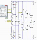
)This is the ultimate version with 2 EF follower output.
It shows rather good values of distortion.
As can be seen the input impedance at 24 Vp input is
48/6.737 = 7k12.
The figures I get are quite low distortion.
At this level the THD is 0.00031%
This is a good value at 36 Watt RMS output.
Now, I expect much lower value of distortion with triple EF.
And considerably higher input impedance.
I be back with a triple emitter follower.
Like in the Leach amplifier.
Attachments
There is actually some temp function in Multisim,You can add a line like 'step temp list 10 30 50 70' to do some temperature drift testing (that's what I do
but I do not bother to learn to use it.
I leave others to setup this circuit in their simulators to see what they get.
But of course I would like to do it
dadod
Elevating voltage, I do not believe in adding diode. The idea is correct, but ....
I prefer CBS240 advice. To add another follower stage.
This will make the output triple EF.
I will test this as it improves gain of the circuit.
Thanks.
Yes I agree triple could be better, but harder to tame(oscilations).
dado
I have tested for AC analysis.
For the triple there is only needed 1.2nF compensation.
While for the 2 EF was needed 10 nF.
The best version so far is one triple EF and with only 10 mA frontend current.
I am just about to complete the FFT of this version.
It shows some tremendous improvenment when testing with 20kHz signal!
I will increase current in frontend and test further.
As one learns about this circuit one could make it better.
Remember this is a new circuit. All we learn will be totally new.
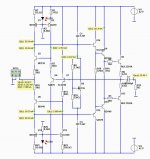
This is the best so far.
Triple EF with only 10 mA through the frontend.
The improvement in 20 kHz is fantastic!!!!
I think I am close to the perfect circuit.
However the input impedance is now only 3 kOhm.
What we would like is something like 10 kOhm.
The figures for 1 kHz and 20 kHz
Triple EF with only 10 mA through the frontend.
The improvement in 20 kHz is fantastic!!!!
I think I am close to the perfect circuit.
However the input impedance is now only 3 kOhm.
What we would like is something like 10 kOhm.
The figures for 1 kHz and 20 kHz
Here is the circuit used:Power Supply +/-42 Volt, 8 Ohm load 6a 10mA
THD 1kHz
04 Vp, 01 Watt THD 0.00007%
08 Vp, 04 Watt THD 0.00010%
12 Vp, 09 Watt THD 0.00013%
16 Vp, 16 Watt THD 0.00017%
20 Vp, 25 Watt THD 0.00020%
24 Vp, 36 Watt THD 0.00023%
28 Vp, 49 Watt THD 0.00027%
32 Vp, 64 Watt THD 0.00030%
36 Vp, 81 Watt THD 0.00033%
THD 20kHz
04 Vp, 01 Watt THD 0.00008%
08 Vp, 04 Watt THD 0.00012%
12 Vp, 09 Watt THD 0.00017%
16 Vp, 16 Watt THD 0.00023%
20 Vp, 25 Watt THD 0.00029%
24 Vp, 36 Watt THD 0.00036%
28 Vp, 49 Watt THD 0.00044%
32 Vp, 64 Watt THD 0.00053%
36 Vp, 81 Watt THD 0.00067%
Attachments
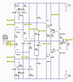
This is the correct numbers of the Triple EF circuit.
I think it is just great.
The 20 kHz numbers are so impressive.
I hope you like what you see.
This circuit deserves a chance.
Can't wait to see someone give it a shot.
I think it is just great.
The 20 kHz numbers are so impressive.
I hope you like what you see.
This circuit deserves a chance.
Can't wait to see someone give it a shot.
Power Supply +/-42 Volt, 8 Ohm load 6a 10mA
THD 1kHz
04 Vp, 01 Watt THD 0.00008%
08 Vp, 04 Watt THD 0.00011%
12 Vp, 09 Watt THD 0.00014%
16 Vp, 16 Watt THD 0.00018%
20 Vp, 25 Watt THD 0.00022%
24 Vp, 36 Watt THD 0.00025%
28 Vp, 49 Watt THD 0.00029%
32 Vp, 64 Watt THD 0.00033%
36 Vp, 81 Watt THD 0.00036%
THD 20kHz
04 Vp, 01 Watt THD 0.00022%
08 Vp, 04 Watt THD 0.00054%
12 Vp, 09 Watt THD 0.00078%
16 Vp, 16 Watt THD 0.00090%
20 Vp, 25 Watt THD 0.00098%
24 Vp, 36 Watt THD 0.00108%
28 Vp, 49 Watt THD 0.00118%
32 Vp, 64 Watt THD 0.00132%
36 Vp, 81 Watt THD 0.00151%
Attachments
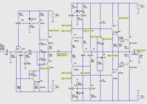
The preamp before this buffer could be a nice discrete opamp or a tube preamp for higher voltage. Then adding the power buffer will make the signal good for loudspeakers.
Normal power amplifiers have input and VAS stage to do the voltage amplification.
In this concept we use a preamp to do the voltage amplification and so we add a buffer for loudspeakers.
I show you only one example here.
This is a good voltage amp. With low distortion.
After this we put the power buffer.
See my diagram and you will understand.
Attachments
Elvee has tried to compare this to his own circuit which has its own thread. He should heed his own advice and only discuss Lineup's circuit on Lineup's thread and Elvee's circuit on Elvee's thread. See his directive when someone promoted an alternate circuit on the Triplington thread.
I don't think I went off topic: I simply remarked that the scheme had been around for quite some time, and provided an example of alternative implementation I could find easily. You chose to discuss it and ask questions, which I answered. Damned if you do, and damned if you don't.
You seem to suggest that this example is irrelevant and is quite different from Lineup's circuit, but I don't think so: apart from minor details like OP devices, the only serious difference is in the bias control: Vbe multiplier for Lineup, and non-switching engine in my circuit. But that is secondary: the noble path works in exactly the same way, and that is in essence what makes the scheme so effective.
As for the diamond buffer, both circuits have one, but in my case the collectors are bootstrapped to the output. This is strictly equivalent, but has a small performance advantage, and more importantly it makes the circuit safer and avoids the need for high voltage transistors for the diamond input.
I think Lineup could use this idea: unlike the rest of my example, this one is safe enough.
Once this equivalence is accepted, it becomes possible to use a NPN in front the NPN and vice-versa, which could improve the offset.
Now, there is an interesting question: why is this type of circuit not as widespread as it seems to deserve?
I think the main reason is that it packs a huge amount of gain in a very small space. This is what gives it its outstanding performance, but it comes at a cost: it is requires a low source impedance, which is unusual but manageable, but the really tricky aspect is the tradeoff between stability, in driving difficult loads for instance, and keeping an acceptable SR and bandwidth.
I chose to make a tricky circuit even trickier, whereas Lineup has opted for a safer, more reasonable approach, but to each his own....
I will follow this thread with interest, to see if clever compensations schemes emerge, this would be a real advance.
PS:
I never posted anything about triplington...
Elvee.
From what I did see of your circuit it has got something like my circuit. We can say the idea is there.
So, I do not mind you mention your circuit here.
I am open minded.
As much as I love Struth I can love you Elvee.
In fact any posting here is something I am happy about.
So, I thank you both. It means a lot to me.
- Status
- This old topic is closed. If you want to reopen this topic, contact a moderator using the "Report Post" button.
- Home
- Amplifiers
- Solid State
- New Lineup IDEA - Power Follower/Output stage