I first realized this problem one day when I turned my system on to listen and saw the midrange undergoing extreme movement while playing due to reproducing some low frequencies (there is no capacitor in series with it to block low frequencies since the system is actively biamped). I performed a complete capacitor replacement on the amp, including the large power supply caps - the low frequency oscillation is still there. I have measured some peaks of 350 mV. This is only in the right channel. Observing the right channel output on a scope you can see the the trace bobbing up and down with the oscillation.
I suspect the problem to be associated wit the DC servo circuitry. Does anyone know which board and section this circuitry is on?
Thanks,
Will
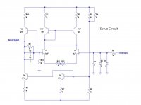
There is a discrete JFET input diff-amp circuit on the main input PCB that performs the DC-servo function. This circuit uses the standard capacitor feedback integrator topology.
There is also an opamp based circuit on the power-up PCB that performs a coarse check for DC shorts in the output stage transistors before soft-start power-up is allowed.
If you carefully look over your main PCB the discrete servo circuit should be similar to the attached topology. A parallel pair of high quality 3uF capacitors are often used for the integrator function. Locating these caps might help you trace the servo circuit on your PCB.
Attachments
I can't seem to find a problem with the DC servo circuit; the related transistors seem to be OK. In studying my scope output watching the DC level fluctuate, it occurred to me if the bias level was fluctuating due to some fault with the auto bias circuit the DC servo would just be trying to compensate so there would be no DC offset on the output. Is there a way I can test the opto-coupler IC?
Thanks,
Will
Thanks,
Will
I can't seem to find a problem with the DC servo circuit; the related transistors seem to be OK. In studying my scope output watching the DC level fluctuate, it occurred to me if the bias level was fluctuating due to some fault with the auto bias circuit the DC servo would just be trying to compensate so there would be no DC offset on the output. Is there a way I can test the opto-coupler IC?
Thanks,
Will
Will,
The only safe suggestion I can give you is to CAREFULLY use your O'scope to compare key signals between the good channel and the bad channel. Study the main PCB to locate key input transistors, feedback points, and Vbe driver transistors. A faulty local power supply could also be the cause of your oscillation. Changes in output bias current causing your oscillation does not make sense to me as an outside guess'er.
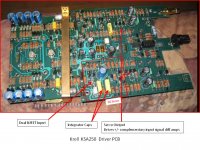
I attached a photo of the KSA250 driver PCB outlining the DC servo circuit we have been discussing.
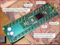
The identified screw hole connects a trace on the output PCB below to the DC servo input. Hence, the amplifier output signal comes from the PCB on the heatsink up through this screw hole to the servo input on the main PCB mounted above. 3D-SOUND. well.... 3D packaging anyway.
")
Attachments
Thanks for the helpful photos Linesource. Do you know what the other optoisolator on the input board is for?
I will check the input differential pair transistors. Working on a live amp seems too risky as some leads are very close together.
Do you think I can swap input boards between the two channels to narrow the problem to either the input or output boards?
Thanks
I will check the input differential pair transistors. Working on a live amp seems too risky as some leads are very close together.
Do you think I can swap input boards between the two channels to narrow the problem to either the input or output boards?
Thanks
Do you know what the other optoisolator on the input board is for?
I will check the input differential pair transistors. Working on a live amp seems too risky as some leads are very close together.
Do you think I can swap input boards between the two channels to narrow the problem to either the input or output boards?
Thanks
Will,
Before you swap driver boards, give some thought to a couple O'scope tests. I often use small Test Hook Clips that can safely spring attach to the lead-in on a resistor or capacitor.
UNPLUG AMP
GROUND THE INPUTs
PUT A DUMMY LOAD RESISTOR ON THE OUTPUTs
Put a test hook clip on the lead wire on one of the 3uF DC servo caps at the output drive side(away from NJET input). This is the output of the DC servo amp.
POWER ON!
xxxxxxx
The second opto isolator monitors the current in an output predriver emitter follower. Too much predriver current implies unsafe output current. This is part of the safe operation circuitry.
xxxxxxx
A change in output bias current should be handled by the amplifier's negative feedback. That's why a fault in the servo circuit feedback, or the complex input circuitry seems more logical. Changing driver PCBs might confirm this without any information for a solution.
What's the iine... Measure twice, cut once.
Too bad I can't post videos here. It is interesting that the DC oscillation goes positive and negative but is slightly biased in positive voltage territory. Just to rule out an issue with the bias circuit on the output board - and avoid having to desolder and solder 28 power transistors again - I plan to replace the bias transistor and IL74 optocoupler first. Do you think any of the input transistors need to be matched if I have to replace them?
By the way, I just noticed your Apogee Full Range avatar. I have biamped Divas powered by two KSA-250s; a version 2 and 3. The amp I am working on now is the version 2. The two DC servo caps are 2uF on mine.
Will
By the way, I just noticed your Apogee Full Range avatar. I have biamped Divas powered by two KSA-250s; a version 2 and 3. The amp I am working on now is the version 2. The two DC servo caps are 2uF on mine.
Will
you can't post video's here but you can post them on youtube and then link them here! for example here is an excellent video showing lots of details about the insides of the big 250's
Krell KSA-250 recapping - YouTube
Krell KSA-250 recapping - YouTube
"Right channel output of a Krell KSA-250 amplifier with no input signal displaying problem with DC oscillation."
Will,
Is the input grounded or just floating open in your video?
The front-end circuitry is complicated. There are both a single ended input and a differential input, plus a mechanical relay for input selection.
The KSA-250 is shipped with shorting pins in the XLR inputs. These pins must remain in the XLR inputs if the units are to operate in the single ended mode. These pins must be removed to connect either unit for balanced operation. The shorting pin connects pins 1 and 3 and grounds the inverted input.
I'm a blind man in a mind field.
""F. PROTECTION CIRCUITRY
The KSA-250 has a sophisticated series of circuits that protect them from dangerous input signals or loads on the output. These circuits also analyze various amplifier functions to prevent speaker damage that may be caused if the amplifier fails to function properly.
There are two protection modes: Input and Output. When the Input Protection is engaged the amplifier will remain on, with the front panel LED illuminated, but it will not pass a signal. This indicates a problem with the input signal caused by the preamplifier or source component. This is most often a DC condition. The amplifier will resume passing signal when the problem is resolved.
When the Output Protection is engaged the amplifier will turn off, with the front panel LED turning off as well. This usually indicates a problem with the speaker wires, their connection, or the speakers themselves. Once the problem is located and resolved the amplifier will turn on normally with activation of the front panel switch. The Output Protection will also engage if the amplifier fails. If the amplifier will not turn on with all inputs and outputs disconnected, please contact your dealer or Krell Service""
Last edited:
Linesource,
I am going to replace the matched input JFETs as I understand this maybe the cause of the problem. The parts, J203 N-channel JFETs are rated at 40V Vds. As these parts are no longer available the Motorola recommended substitute is rated at 25V. Do you think this would be a problem in the circuit?
Thanks,
Will
Linesource,
I am going to replace the matched input JFETs as I understand this maybe the cause of the problem. The parts, J203 N-channel JFETs are rated at 40V Vds. As these parts are no longer available the Motorola recommended substitute is rated at 25V. Do you think this would be a problem in the circuit?
Thanks,
Will
Linear systems recommends this part http://www.linearsystems.com/datasheets/J201.pdf
rated at 40V
Cheers,
Eric
Will,
You might give some thought to simple tests that can confirm that the DC servo is the source of the oscillation. The DC servo circuit that was pictured earlier is connected to a ???K resistor that then drives the feedback inputs of the main dual diff-pairs. If you can locate this resistor on your PCB you could unsolder the resistor lead coming from the Servo. NOTE: the servo output will still go to the safe operation circuitry(op amps), but this should function just as before. We are only removing the servo from the input feedback point. If this removes the oscillation, then the servo circuit is likely at fault and needs additional testing... JFETS? ServoCaps? Local power supply Caps? Connection link to safe operation circuitry?
At the same time you could solder a test wire to the pad where the resistor lead was unsoldered and lifted, and use an O'scope to also monitor the now isolated DC servo output.
You can probably come up with other servo test ideas.
Remember from the PCB pictures that the input to the DC servo comes through a metal spacer that is attached by screws to the output transistor PCB. A funky mechanical connection.
GROUND THE INPUTs
PUT A DUMMY LOAD RESISTOR ON THE OUTPUTs
- Status
- This old topic is closed. If you want to reopen this topic, contact a moderator using the "Report Post" button.
- Home
- Amplifiers
- Solid State
- Krell KSA-250 low frequency oscillation