Hi Guys
There are contradictions in the relevance of stable Vq.
One one hand, Self extols the virtues of stable Vq and even suggested this might be a new insight. Supporting that claim in a manner of interpretation are the distortion specs of his Trimodal amplifier. When the class-A mode is pushed hard and reverts to class-B - he calls this class-AB - THD is higher than for either class-A or class-B. In both latter cases, Vq is constant but for AB it is not.
The above might suggest a flaw with sliding bias methods as Vq will vary over the signal cycle. On the other hand, one of Self's conclusions about certain circuit behaviour is that the circuit portion turning 'off' has the greater impact on THD. This would imply that disallowance of turn-off would obviate the distortion, giving credence to the sliding bias, class-i et al techniques.
It would be nice to completely eliminate distortions, but that is not likely to happen in this universe. For my own listening and construction, moving the THD artifacts away from the power range most often used is sufficient to make THD within that used range vanishingly small. The methods I referred to in my books and elsewhere above, achieve this in a simple way. Most tend to move the amp to class-A, or at least greatly increase the class-A region. Look at my posts in the Lineup buffer thread to see a circuit app.
Never posted to the circlophone threads but read them to see if there was anything worth learning about. Same with the tringleton.
Have fun
Kevin O'Connor
There may be a good explanation or reason, but I'm unclear on how Vqs changing while an AC signal is present ought to have any effect different than the presence of the AC signal? At any instantaneous moment the voltage present is Vqs +/- [AC signal]. There is some question as to if this is a voltage or a current, or a combination of the two I suppose... perhaps I am naive about how this works, entirely possible. But it seems unclear to me why it makes any difference.
As far as non switching output stages intuitively it seems to me that there are two choices as how to make it happen, maybe three:
- never apply an AC signal that drives "below" the Vq point.
- apply a signal that is more or less the inverse of the driving signal to each half of the output stage only when that signal is traveling "south" of Vq (selective inverse cancellation).
A trick is done in AM ham transmitters called the "3 diode limiter" that prevents "baselining" and permits positive modulation in excess of 100%. Baselining is when the modulation is sufficient to overcome the carrier amplitude and causes a cutoff, which results in briefly having zero power out, and the transient going off and coming back on causes severe IM products.
I'm not sure, since the Kendall Perry circuit isn't immediately obvious to me, but after reading the Linear Audio article once or twice, I got the sense that his method is more or less a "see-saw" sort of approach where the drive in one phase forces the current in the side headed toward cutoff back up before cutoff is reached. If this is done on a low(er) level circuit then only normal bias is required in the output stage since the signal sent never sends each half toward full cutoff... which if I have this part correct is far more elegant than trying to wrap around a loop to do this job. And, even if I have the Kendall-Perry idea all wrong, and I may well, that's how I would envision doing it.
_-_-bear
Hi Guys
Bear, your interpretation of the class-i circuit is correct. However, the idea that the correction for crossover elimination can be moved forward in the circuit is incorrect. Unless Vq is massive by way of operating the output stage in class-A, then crossover distortion will occur as the signal can turn off one side of the output or the other.
Most transmitters are SE so cutoff is related to one side of the signal being excess in amplitude. In this case bounding the signal in one direction keeps cutoff from occurring. Because the final output in most transmitters is class-C, the "saturation" side of the wave is less problematic.
There are two mechanisms involved at the crossover point and two distortions that result: The frst is actual crossover distortion caused by the nonconjugate nature of the transfer curves of the two halves of the output stage. The second is switch-off distortion, likely caused by charge storage in the devices being turned off. Pages 180-184 detail Self's study into this ((Audio Power Amplifier Design Handbook 5th ed.). Where thermal compensation to cancel Vbe variance under load and with temperature variations assures Vq will be maintained constant, the traditional discussion ends there. Direct tracking of Vq is not considered except for specific designs, such as class-A amplifiers where Vq corresponds to a very high Iq that presents the possibility of thermal runaway. It is obvious that such a direct-control approach of Vq can readily be applied to lower idle currents.
As stated previously, part of class-i's promise is to allow low idle currents and cool operation of the output stage without crossover distortion. Direct Vq control is the surest way to achieve this but the class-i engine may be too fragile (sensitive to component parameters) to achieve it in a practical fashion.
Have fun
Kevin O'Connor
Well the issue of crossover distortion is one of addition at the xover point. Eliminating the turn off introduces some issues it seems to me. The "Gm doubling" that I first saw published by Ben Duncan, which addresses that exact point where the output stage goes from two conducting devices to a single remains to be considered. Even if the amp without device turn off is "high bias, there is still a point in the transfer curve where there is a hand off.
Now, conceptually one might think of the non-switching amplifier's output stage as two SE amps, where they are more or less biased in class B, but there is a soft limiter on the negative going AC drive signal so that there is no hard transition and the SE output stage is never driven off completely. But the two transfer curves still must be made to meet.
It seems to me that perhaps the question revolves around the sonic deficits or lack thereof for the switching artifacts vs. non-switching linearity at the xover point(s).
Or if there is a way to skin both cats, for the best of all worlds.
I don't have that answer, but am interested in that question.
_-_-bear
Hi Guys
In class-A the issues of crossover and switch-off distortion are completely eliminated; those deficiencies are only present in class-B and -AB.
The audibility of these distortions has been well documented elsewhere... maybe even in St. Elsewhere?
Gm doubling is itself a myth. The issue is the reduction of gm either side of the mutual conductance zone. Even here, Leech dismisses it completely suggesting that the gm for the _whole_ output stage depends primarily on the load, with the result that gm is essentially the reciprocal of the load resistance. See his article on his site.
Oliver introduced the gm-doubling term in the 1960s, and explained a way to minimise its effect by setting Vq equal to 26mV, then adjusting Re accordingly for a given idle current. This is basically the approach Cordell follows, and one ends up with large Re values as a result. The problem is that Re sets the output impedance of the amplifier, influencing damping and high frequency response.
Gain variation near the crossover point is the main issue, and this is based on a combination of factors already listed above.
One possible approach is to simply add two current sources in parallel with the driver devices, combined with a direct-control current-set circuit. The latter locks Vq while the CSs provide a minimum current through the 'off' device base to keep that output from actually going completely 'off'. This is essentially what class-i is trying to do, but they do it in a more "clever" way.
Have fun
Kevin O'Connor
Kevin, Elvee has made some considerable contributions here over a pretty good period of time. He's put his circuits up to scrutiny. I don't know him personally either and we're not internet buds either.
Self and Cordell, as you know are participants here.
It seems like you're pretty good at this EE stuff. If you want to test yourself, jump into the Opamp Open Design thread and see how you fare. Likely ok, but expect to be challenged, I'd reckon. Or John Curl's Blowtorch thread, if you want more to chew.
It's easy to sit on the sidelines and complain or snipe, much harder to play the game.
For me, I am just interested in anything and everything that anyone can bring to the table, right or wrong, since that causes people to think and discuss, and that brings illumination and sometimes understanding.
_-_-bear
Mods, sorry for a little OT here...
Kevin, as I said before if you want to talk privately, do it privately, as in PM or email. Since you keep bringing it up, my email suggested (among other things) that your product for guitar amps, having made certain claims in strong language, was rather an unknown quantity and that you might want to put up some clips that illustrated that it worked as featured... whatever. It's rather irrelevant.
As far as your books, I never heard of you before you posted here and I followed your link to your website. Never heard of you, your company or your books before that. Your books appear to focus on guitar amps, not low distortion high end hi-fi design. No reason that I can see for thinking otherwise.
It is funny how different people read other people differently, in person and in print. I never detected any edge at all to Elvee's posts. Do keep in mind he is European, and his first language is likely not English? He seems to have answered lots of people and come up with some neat designs - regardless of their original source. After all almost nothing has not been done before, right? I don't need to defend Elvee, as I said before.
As far as my own posts, I try to be positive and ask questions when I don't know the answers. I also try to ask questions when i do know the answers, depending on who is participating and what the audience is...
You might find that Curl does much of the same, only he actually knows a bunch more than I do... as do a whole lot of folks on here. Which is why this is a high class forum, btw.
How about Wurcer, he only came up with the 797? Maybe other stuff he doesn't take credit for in public... that's in the past too.
And as far a their contributions, Paul McCartney hasn't written a good song in a long time, but he IS still a Beatle.
You might just buy the copy of Linear Audio, or subscribe?
Jan Didden is on here too...
Myself, my business? I am semi-retired right now. Not bitter at all, maybe a tad frustrated at my private personal challenges, but that's private, eh?
I understand that it is difficult to know how one's writing comes across. So one might find ways of getting independent feedback, if one so desires? Just a thought.
_-_-bear
PS. it is important to also keep in mind that this is a DIY site, and the level ranges from absolute noob through world class... it's not a graduate PhD seminar. (although topics may reach that level)
Well, well...Hi Guys
"Unity reference" is of course, yourself, Elvee, as you set yourself upon your golden pedestal above the rest of the world.
For myself, I am content to be a part of the Earthbound. Karl Marx had great ideas; it was the implementation by others that gave it a black eye. As for keeping company like Self, Cordell, Leech, Blomley, Baxandall... I like this crowd a lot better than where you seem to be seated.
Let us try to forget personal attacks and concentrate on technical matters.
For me, a glass half empty is the same as a glass half full, but others may differ.
I more or less agree: that is the reason why I placed the sign ~ in front of doubling.As for gm-doubling - Oliver's term, also a great engineer in the early days of ICs - it is misnamed.
Actual doubling could only happen in extreme overbias situations.
What is generally observed is an increase of the apparent transconductance when the stage is overbiased.
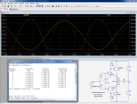
This can be illustrated with this example. It is a CFP because it makes the phenomenon very clear-cut and easy to observe.
First, the situation with underbias: there is an increase of the output resistance (1/gm) in the crossover region, leading to Xover distortion.
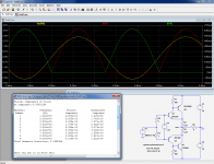
Second, the stage is properly biased and the THD is minimal. Note that it is almost pure second harmonic, meaning it is caused mainly by the poor complementarity between devices, not by the biasing level.
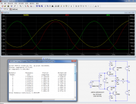
And finally, the overbiased case: the THD has increased again, and if we look at the currents waveform, we see that in the part where they overlap, there is a change in slope: both output devices now contribute to the output signal, and each reduces its contribution by an inherent feedback mechanism, but the effect of the "~doubling" (see caveat above) remains, as the THD shows.
I have used a CFP because it shows very neatly the changes in slope, but the effect is present in any stage, even if it is somewhat blurred.
Why would one want to overbias an output stage, knowing that it leads to increases Xover distortion?
There could be a number of reasons.
-Although the THD in under/ overbias situations is comparable, the underbias one is much more objectionable from an audibility perspective, and since the bias setting is not very accurate, one prefers to remain on the safe side, even if it leads to increased distortion.
-Some people advocate a class AB, with a strong and wide A region, to move Xover problems towards a higher listening levels. I am not sure it is a good idea, but I do not judge the validity of one philosophy over the other, I simply examine the consequences.
-When the stage is optimallly biased, the output resistance is not flat for the Xover region, it has "ripples", which some feel are more detrimental than a continuously too low resistance. Here again, it is a matter of taste.
Attachments
Hi Guys
Elvee, to me it looks like your graphs and explanation target internal gm variations as at least one source if not the major source of crossover distortion. The optimal bias point, which Oliver tried to specify, does minimise some of the negative result of the variation but the variation is always present.
The reason this comes to mind is twofold: First, a common fix for large signal nonlinearity (LSN) is to parallel more output devices. This has multiple effects itself: reducing beta droop, reducing the current through each device, reducing output impedance, etc, all of which widen and flatten the gain wobble of the output stage. There is also a potential to increase the "internal" gm of the stage depending on how you treat the idle current.
The second reason is when you consider the class-A situation. Internal gm is high as the current is high, so internal resistance is low - the "slope" I believe you are referring to. Yet, this condition could be interpreted in one way as being waaaaay overbiased, but the side effects of such a condition are not present until you drive the circuit out of class-A into -AB, as Self demonstrated. Again, this points to switch-off issues. Under-, over and optimal-B bias all have switch-off characteristics but the narrowness of gain wobble varies, along with the THD profile.
Bear, the portion of email you referred to was not what made me wonder about you.
As far as my history and views go, I've been involved with audio since 1974 and what you call "high end" since 1982. Most of my work in electronics has been designing for other companies, with the guitar amp and book biz just being the most visible and direct marketed part of what I do. My books go way beyond what is historic in the MI world and pulls in ideas from other disciplines of electronics - part of why the books are industry standards and have influenced every builder in MI. I don't consider circuit ideas to be "exclusive" to one end of the business or the other, so there are "highend" ideas in the guitar amp books that will be part of and expanded upon in the new range of hifi books we are working on.
Our site is one of the oldest on the web, but we keep it simple to load even for text readers. Our philosophy is that all of this should be fun. Whether you create music or simply listen to it; whether you build amps or simply read about them; none of this is critical were the bomb to drop, so as an entertainment it should be enjoyable. Our books, writings, web posts and site all convey this message. People who use our technologies and believe in the same things have created forums in support, such as the PowerScaling.com forum, set up by Mickey Corrieri of Soultone Amps. It is not my forum but I contribute to it and fully support it. Our technologies have been incorporated into all kinds of products and brands, so we must be doing something right. We never make a claim that our product cannot fully exceed.
I joined this forum because it seems to be relatively free of immature flaming - instead it has intellectual flaming, haha - and there is lots of talent here. I've made lots of contributions here since I've joined, as it is part of who I am and what I do - learning and sharing and trying to eek out a living. I've learned a lot, as well, and have seen sides of "heroes" that take away some of the shine but not always the glint.
Have fun
Kevin O'Connor
Last edited:
Multiple output devices or not, keeping the total idle current equal, you will get the same gm wobble at the crossover region.
The (external) emitter resistors contribution to output Z would be less but if increased
in inverse proportion of the current decrease, for obvious bias stabilization , then it would change nothing.
Hi Guys
wahab, I can't follow what you mean.
Cordell follows Oliver exactly when adding more output pairs: each pair has the same idle current and Re values, so idle current goes up with each pair added.
Self is ambiguous about idle current versus number of pairs of outputs.
Leech explicitly stated that a given idle current corresponds to lowest THD for the whole output stage, so the pairs could share the current without altering THD.
Each approach has its own impacts; the ambiguous one likely the most...
Have fun
Kevin O'Connor
Yes, precisely because all the (static) linearity/transfer problems in the Xover region can be traced to/interpreted as 1/gm variations and non-linearity.Elvee, to me it looks like your graphs and explanation target internal gm variations as at least one source if not the major source of crossover distortion.
A proof of that is that all problems vanish if the load is removed
As others remarked, if the paralleling simply means spreading the same current between multiple devices, little will change.The reason this comes to mind is twofold: First, a common fix for large signal nonlinearity (LSN) is to parallel more output devices. This has multiple effects itself: reducing beta droop, reducing the current through each device, reducing output impedance, etc, all of which widen and flatten the gain wobble of the output stage. There is also a potential to increase the "internal" gm of the stage depending on how you treat the idle current.
If identical stages are stacked, and the initial Iq is multiplied by n, the relative variation of gm will have proportionately less impact, unless the load is reduced in the same proportions
That is a matter of taste as I said above, but fundamentally I do not see the logic of designing a 50W amplifier to be used only up to 2.5W.The second reason is when you consider the class-A situation. Internal gm is high as the current is high, so internal resistance is low - the "slope" I believe you are referring to. Yet, this condition could be interpreted in one way as being waaaaay overbiased, but the side effects of such a condition are not present until you drive the circuit out of class-A into -AB, as Self demonstrated. Again, this points to switch-off issues. Under-, over and optimal-B bias all have switch-off characteristics but the narrowness of gain wobble varies, along with the THD profile.
Except for pure class A, there will always be a class switching somewhere, and the later the switching, the higher the THD.
Class AC of J Broskie is an interesting way round this problem.
It is not the universal solution to everything though: first it is a pretty hot class, and second there are problems of accuracy because the hand-over between devices has to be accurate for optimum results, and that is not necessarily easy to achieve.
It is certainly a clever solution deserving attention
Post53 plots are very interesting and confirm what has been described many times before.
I note, for those that haven't spotted it yet, that the optimally biased has substantially 2nd harmonic, whereas the under-biased and over-biased have gross amounts of odd order distortions. Even the ninth of the under-biased is still more than the second.
In the over-biased operation the 7th and 9th have fallen to lower than 2nd. That seems to indicate a "sound" quality that may be better than under-biased. This is what an earlier poster stated, that if not optimally biased then over is better than under.
These high and odd order are Spikes that get added to the harmonious signal. It is the relative "size" of the spikes that makes them audible. They are narrow and thus contribute less to total percentage distortion than would a wide harmonic addition of similar "size". This gives an under representation of the "size" of the spike contribution to the signal resulting in the misleading impression that low numbers for crossover distortion cannot be heard.
0.1% of crossover distortion will sound quite different from 0.1% of second harmonic distortion where there are unmeasurable levels of the higher orders.
A blanket philosophy has developed that 0.01% of THD is inaudible.
I don't have the expertise, nor the instrumentation, to challenge that philosophy.
What I can do is recognise that 0.01% of low orders of THD are a very different animal from 0.01% of high and particularly odd orders of THD.
Simple total THD tells us virtually nothing, at least that's what I am led to believe. Aksa is a proponent of a gradual declining of all orders from 2nd down to wherever they become inaudible and/or unmeasurable, as an indicator of good sound.
Very few, if any commentators, have come to my notice to challenge this philosophy.
On the basis that some of the spikiness of crossover is what makes for bad sound then Optimal ClassAB bias must the the only way to progress if ClassA is energy wasteful and to be avoided by all that want to save the Earth.
Last edited:
Hi Guys
Elvee, have you ever measured how much power your own listening system and loudness preferences require? I have, and for me it is less than 1W per channel. So, for my own use, amps with a wide class-A region that covers the power I may ever use means that it is highly unlikely that I will ever push them to the point of class transition. Even if I did, the sound would be in excess of what I can humanly process so it is irrelevant. Maximum loudness here is about 90db, but more usual levels are 60db or so.
At that 1W/ch level, I could not listen for very long. More usual listening levels require one-hundredth the power and less.
Class-A eliminates major distortion mechanisms when implemented correctly. If you make an accurate assessment of your own power needs, then it is a highly viable and easy solution to achieve very-low THD. Distortion profiles are not much in question these days by anyone who knows how they impact sound. That an arbitrary THD figure is "inaudible" has always been the belief of a segment of the audio community, but it is again not what most knowledgeable designers believe.
Have fun
Kevin O'Connor
Last edited:
As others remarked, if the paralleling simply means spreading the same current between multiple devices, little will change.
The combined Gm of the multiple pairs will be the same as the single pair
but the total value of the external emitter resistors (if their value is kept
the same as the single pair case) will be divided by the n number of output pairs.
Assuming 100mA total Iq and 0.22R emitter resistors , a single pair
output Z is about 0.24R , two pairs will yield 0.185R , 0.166R/3Pairs
and so on ,converging to an infinite number of pairs as yielding the
output Z of an emitters resistors less single pair ...
RE
Hi Wahab,
You're right and I like to add that in order to minimize the 'gm wobble' you have to increase the RE's inversely proportional to the number of OP devices (assumed that the total Iq is held constant, of course). So, as said before, nothing will change.
Cheers,
E.
The (external) emitter resistors contribution to output Z would be less but if increased
in inverse proportion of the current decrease, for obvious bias stabilization , then it would change nothing.
Hi Wahab,
You're right and I like to add that in order to minimize the 'gm wobble' you have to increase the RE's inversely proportional to the number of OP devices (assumed that the total Iq is held constant, of course). So, as said before, nothing will change.
Cheers,
E.
I broadly agree, but don't fall into the trap of "hearing with your eyes": you have access to technology allowing you to see and plot the amplitude vs time, and it is tempting to draw audio conclusions from the visual appearance of the waveforms.Post53 plots are very interesting and confirm what has been described many times before.
I note, for those that haven't spotted it yet, that the optimally biased has substantially 2nd harmonic, whereas the under-biased and over-biased have gross amounts of odd order distortions. Even the ninth of the under-biased is still more than the second.
In the over-biased operation the 7th and 9th have fallen to lower than 2nd. That seems to indicate a "sound" quality that may be better than under-biased. This is what an earlier poster stated, that if not optimally biased then over is better than under.
These high and odd order are Spikes that get added to the harmonious signal. It is the relative "size" of the spikes that makes them audible. They are narrow and thus contribute less to total percentage distortion than would a wide harmonic addition of similar "size". This gives an under representation of the "size" of the spike contribution to the signal resulting in the misleading impression that low numbers for crossover distortion cannot be heard.
0.1% of crossover distortion will sound quite different from 0.1% of second harmonic distortion where there are unmeasurable levels of the higher orders.
A blanket philosophy has developed that 0.01% of THD is inaudible.
I don't have the expertise, nor the instrumentation, to challenge that philosophy.
What I can do is recognise that 0.01% of low orders of THD are a very different animal from 0.01% of high and particularly odd orders of THD.
Simple total THD tells us virtually nothing, at least that's what I am led to believe. Aksa is a proponent of a gradual declining of all orders from 2nd down to wherever they become inaudible and/or unmeasurable, as an indicator of good sound.
Very few, if any commentators, have come to my notice to challenge this philosophy.
On the basis that some of the spikiness of crossover is what makes for bad sound then Optimal ClassAB bias must the the only way to progress if ClassA is energy wasteful and to be avoided by all that want to save the Earth.
In some cases both are in good agreement, but that is far from being a general rule: two shockingly different signals (visually) may sound exactly identical, whereas one shockingly distorted signal (audibly) may look almost identical to a perfectly clean one.
The fact is that an underbiased OP is one of the most offending sound you can hear: completely unnatural, unpleasant and detectable at tiny levels
Unfortunately, I have to listen at levels well under 1W, and probably <100mW: I run into problems with wife, neighbors, etc as soon as I try to push the volume.Hi Guys
Elvee, have you ever measured how much power your own listening system and loudness preferences require? I have, and for me it is less than 1W per channel. So, for my own use, amps with a wide class-A region that covers the power I may ever use means that it is highly unlikely that I will ever push them to the point of class transition. Even if I did, the sound would be in excess of what I can humanly process so it is irrelevant. Maximum loudness here is about 90db, but more usual levels are 60db or so.
At that 1W/ch level, I could not listen for very long. More usual listening levels require one-hundredth the power and less.
Class-A eliminates major distortion mechanisms when implemented correctly. If you make an accurate assessment of your own power needs, then it is a highly viable and easy solution to achieve very-low THD. Distortion profiles are not much in question these days by anyone who knows how they impact sound. That an arbitrary THD figure is "inaudible" has always been the belief of a segment of the audio community, but it is again not what most knowledgeable designers believe.
Have fun
Kevin O'Connor
I personally could content myself with a small class A amplifier, even a small class AB is vast overkill, but as I said above, that is not a question of my personal taste (or limitations).
If I design a 50W amplifier, I primarily want it to keep its specs for its whole ~0 to 50W range.
If you don't aim for perfection, there isn't half a chance you can reach half-perfection.
Agreed, but with a low Iq, keeping emitter resistors that low makes them decorative: for them to be effective, they have to drop at least one or two tens of mV, preferably a little more.The combined Gm of the multiple pairs will be the same as the single pair
but the total value of the external emitter resistors (if their value is kept
the same as the single pair case) will be divided by the n number of output pairs.
Assuming 100mA total Iq and 0.22R emitter resistors , a single pair
output Z is about 0.24R , two pairs will yield 0.185R , 0.166R/3Pairs
and so on ,converging to an infinite number of pairs as yielding the
output Z of an emitters resistors less single pair ...
- Status
- This old topic is closed. If you want to reopen this topic, contact a moderator using the "Report Post" button.
- Home
- Amplifiers
- Solid State
- Class i