I bought a brand new unused Z3 a couple of years ago. When I have finished wiring up my external passive x/over for my Heybrook Sextets I will first use a dummy load in case of any serious issues - would not want to naff the Sextets.
If I have any heat issues I will use the computer fan underneath as I do for my hybrid h/amp. Strange that some have no heat issues and others do, could it be a case of bad final assembly and/or final inspection issues?
If I have any heat issues I will use the computer fan underneath as I do for my hybrid h/amp. Strange that some have no heat issues and others do, could it be a case of bad final assembly and/or final inspection issues?
Have you checked the offset adjustment? I have seen comments about the channels being very different. On my short list of projects.
I haven't yet, but it's on my list. Do you have a procedure for it? Sure would like to have a service manual but haven't seen one.
Gary
Strange that some have no heat issues and others do, could it be a case of bad final assembly and/or final inspection issues?
I think there is just something wrong with this one. I don't think it is that common a problem.
Gary
Probably the same procedure as the big HCA series. I think a manual is available for those. I'll have to look at the schematic carefully. Mine does not show any DC on the output.
Put mine on the bench last night. Power spikes were @ -30 dB. For sure it needs new power supply caps. Actually, I am sure it needs 10 times as large. Going to see what will fit in it.
Put mine on the bench last night. Power spikes were @ -30 dB. For sure it needs new power supply caps. Actually, I am sure it needs 10 times as large. Going to see what will fit in it.
Hmm. I wonder if you have to stop the servo first. I would look at the DC on the base of Q106 and 206 to see if they are the same. Only way I know to get good quiescent DC readings is to load it into Spice. Hardest part may be figuring out what the transistors are. Looks like the schematic has "Parasound" numbers. No value on the cap on the base ofQ205. They intentionally did not make it easy.
Gad, a 45W amp and the heat sink for a 4.5. Looking how to improve, replacing C105/205 with a film. C101/201 and C105/205 probably need replacing. I might see is I could get larger C101/201.
Other than more supply rail cap and heat sink, looking for things to tweak. Red LEDs are more stable than the diodes in the IPS and VAS CCS. One would have to model it it get the values need. Overall, only obvious short coming in no CM in the IPS LTP. Very good overall circuit design. Not sure I am going to fool with mine as I don't actually need it for anything. Ordered new PS caps and wil just sell it. ( in GOOD condition, unlike so many things on e-bay)
About twice mine, but yea, good. DC servo so it should be. Look carefully at the schematic and compare the quiescent DC all around the VAS.
Any electrolytic in the audio path that you can replace with a film of the same value is a reasonable improvement. Any electrolytic in the path over 7 to 10 years old should be replaced in kind. Really, the only glaring issues are more as a result of the too small package than circuit. They should have made it 2U high. No magic fixes, nothing like many well known amps by bigger companies that have pages of possible improvements.
I decided it is what it is and will just do the caps and sell mine. I thought about re-packaging it in a bigger chassis with real heat sink, real power supply caps and the two or three small things I should change, but reflecting, I would just buy a New Classic. ( or if I wanted a monster, another HCA2200 Mk II. )
I use whatever caps Mouser has that fit. Nic or Pan I prefer but have no data to prove it. I suggest any new is better than some deemed audiophile old. On film, polystyrene is almost gone, so poly-pro is the optimum choice but even a mylar is a huge step over electrolytic. Do the 90% fix and don't worry about the last 1%.
Checked the DC offset last night, 1.8 mV for both channels, so everything is good there.
tvrgeek, I thought about replacing C105/205 also. What would you use?
Gary
I actually meant C101 and C201, input caps....
Gary
Well, they are 10uF, 50V. I suspect the space on the board would not allow much difference. SOP for an electro coupling cap, more than 10 times what calculation suggest.
Now if it were me, I might try and stuff a .1uF film there. It would give a roll off of 35 Hz, Looks bad on paper, but most reasonable engineering. May help to keep a small speaker excursion in check.
Now if it were me, I might try and stuff a .1uF film there. It would give a roll off of 35 Hz, Looks bad on paper, but most reasonable engineering. May help to keep a small speaker excursion in check.
I found the biasing procedure (attached) on another audio forum. It comes from Parasound. It has a generic procedure with different bias values in a table for each amp. The ZAmp is the last in the list.
I set the bias on my amp and nothing seems to have changed. It wasn't off very much.
I ran the amp at 45 watts, both channels, for 5 or 10 minutes and it never went into protect mode. I'm beginning to wonder if the prior owner knew what they were talking about. It doesn't have feet on it, so I'm wondering if maybe they ran it in a tight spot with no ventilation.
However; the left channel still has a high THD, .1%
So I'm going to work on that problem.
Gary
Attachments
Yep, I drove a Triumph TR7 in high school and college, been there done that!
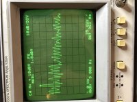
Since my last post I acquired an HP 3582A audio spectrum analyzer. Still learning to use it, but it does show what the problem is. Just not WHERE, yet anyway.
See the attached photo,
What your seeing is the monitor output of my HP8903A. It's an RMS average of 16 samples. Basically it shows just the noise (1 kHz fundamental removed). It very clearly shows odd order harmonics. The marker is on the 3rd harmonic.
What I'm thinking is that odd order harmonics are caused by clipping? Need help here.
Any chance it's a bad cap somewhere?
I don't see any clipping in the output, see the attachment.
If anyone has any advice I'm all ears.
Thanks
Gary
Attachments
Just getting back to this project.
A repair of an HP 8903A got in the way.
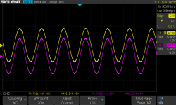
Below is another spectrum analyzer shot of the left and right channels at about 40 Watts both channels and 1kHz. The waveform are from the monitor output of the 8903As. So it's just the noise.
The left channel (top trace) is 20dB higher than the right channel. It just all across the band width.
The second shot is a pic of the THD from the front of the 8903As. The higher number .0532 is the left channel. As you can see the right channel is in spec.
I'm not sure what to look for; transistor, cap, something else?
Anyone have any ideas?
Gary
A repair of an HP 8903A got in the way.
Below is another spectrum analyzer shot of the left and right channels at about 40 Watts both channels and 1kHz. The waveform are from the monitor output of the 8903As. So it's just the noise.
The left channel (top trace) is 20dB higher than the right channel. It just all across the band width.
The second shot is a pic of the THD from the front of the 8903As. The higher number .0532 is the left channel. As you can see the right channel is in spec.
I'm not sure what to look for; transistor, cap, something else?
Anyone have any ideas?
Gary
Attachments
![IMG_6617[1].jpg](/community/data/attachments/825/825455-01152c2827f2de20554be4694661f37e.jpg)
![IMG_6618[1].jpg](/community/data/attachments/825/825481-7cf1f0996190d12725cfd4f206708f02.jpg)
That's great info Gary, I have a HP 3582A myself but not an Audio Analyzer, nice piece!
In my case I honestly only changed the transistors and the 0.22r emitter resistors and considered it done, didn't even matched the transistors or anything...
But yes that little amp gets burning hot, I'll pop it open again and check the bias with that document you shared!!
Thanks Again!
In my case I honestly only changed the transistors and the 0.22r emitter resistors and considered it done, didn't even matched the transistors or anything...
But yes that little amp gets burning hot, I'll pop it open again and check the bias with that document you shared!!
Thanks Again!
That's great info Gary, I have a HP 3582A myself but not an Audio Analyzer, nice piece!
In my case I honestly only changed the transistors and the 0.22r emitter resistors and considered it done, didn't even matched the transistors or anything...
But yes that little amp gets burning hot, I'll pop it open again and check the bias with that document you shared!!
Thanks Again!
Thank you
Gary
Did some more probing around and discovered that the 15V supply is actually 13V and the -15V supply is actually -18V. Not sure why I didn't check it earlier, I did check the +- 35V and it's good.
So maybe that's part of the problem.
Of course my prob slipped and I blew the fuse. I don't have any so I have them on order.
I hope that's all I blew!
Gary
So maybe that's part of the problem.
Of course my prob slipped and I blew the fuse. I don't have any so I have them on order.
I hope that's all I blew!
Gary
- Home
- Amplifiers
- Solid State
- Schematic for Parasound Zamp ver 1