what is the difference between loop gain and open loop gain?
What do the .op statements look like for the three conditions you are examining, closed loop gain, loop gain and open loop gain?
Is loop gain the 1/NFB ratio = beta?
Loop Gain(LG) is difference between Open Loop Gain(OLG) and Close Loop Gain(CLG), means OLG-CLG=LG. LG is effective Negative Feed Back at different frequences.
You can't use .op (compute the DC operating point treating capacitance as open circuits and inductance as short circuits) to simulate LG, CLG or OLG, you use .ac for that.
No , but about the schematic itself or rather the sims,
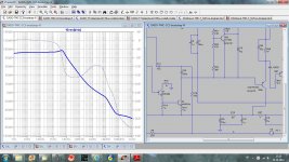
how did you compute the gain/phase response.?...
I hopped for layout comment, as layout discussion in other thread was quite interesting and I tried to follow suggested improvements.
Do you mean LG or CLG?
For LG I do with TMC resistor init and out of Midlebrook probe. Look at attached diagrams.
dado
Attachments
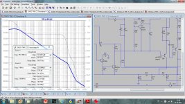
It was about the CL phase and gain responses.
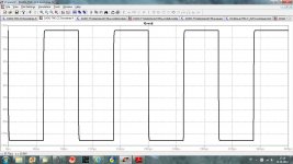
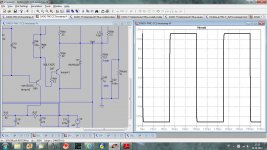
Anyway to check stability you can use a square signal
and parralel a 10nF to 100nF cap with the load , it is often
quite revealing.
I am not sure I understand what you want to know about CLG. How I did the CLG simlation?
I don't have working prototype yet to do Square wave test(I did it on similar standard TMC circuit in my other thread).
Your TMC resistor has quite low value and this generaly reduce considerably
the phase margin once the output is capacitively loaded.
As for square wave test i was speaking in simulation , not in real life ,
as the simulator provide a good estimation of an amp behaviour in this matter.
the phase margin once the output is capacitively loaded.
As for square wave test i was speaking in simulation , not in real life ,
as the simulator provide a good estimation of an amp behaviour in this matter.
Can you post the actual spice .asc for each of the tests, clg, olg, lg with the appropriate .ac activated so that we can see the differences? and run these if we want to duplicate your results.
If you add a .txt or a add .zip to the xxxxxxxxx.asc file name, the Forum allows these to be attached. Or replace the .asc with either .zip or .txt
If you add a .txt or a add .zip to the xxxxxxxxx.asc file name, the Forum allows these to be attached. Or replace the .asc with either .zip or .txt
Here is zip file containig .asc file and models files. Unzip it in the same directory and just run simulation.
There are .tran .ac defined but just one active (.tran or .ac) and others passive(;tran ;ac)
Input generator V4 could be changed from sinus to square just copying the lines already there:
SINE(0 {sqrt(.75)} {freq})
or
PULSE(.5 -.5 0 10ns 10ns .05ms .1ms 8)
there one .ac for (for CLG or LG)
;ac dec 1k 1 1G
and two .tran square and sinus
.tran .4ms
;tran 0 {simtime} {dlytime} {timestep}
dado
Attachments
got it to run.
Thank you.
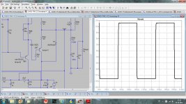
The square wave is applied to the normal audio input and passes the normal RF attenuator. This slows down the step response of the sq considerably.
To stress the circuit more, the RF attenuator should be opened up a lot, maybe a factor of 10, or maybe a lot more. Changing C2 to 22p may give a different result, But it may be that 2pF is more appropriate. But don't go to far. An ultrafast step of the squarewave may be too stressful. How do we adjust the pulse parameters to change the slew of the pulse?
Thank you.
The square wave is applied to the normal audio input and passes the normal RF attenuator. This slows down the step response of the sq considerably.
To stress the circuit more, the RF attenuator should be opened up a lot, maybe a factor of 10, or maybe a lot more. Changing C2 to 22p may give a different result, But it may be that 2pF is more appropriate. But don't go to far. An ultrafast step of the squarewave may be too stressful. How do we adjust the pulse parameters to change the slew of the pulse?
Last edited:
got it to run.
Thank you.
The square wave is applied to the normal audio input and passes the normal RF attenuator. This slows down the step response of the sq considerably.
To stress the circuit more, the RF attenuator should be opened up a lot, maybe a factor of 10, or maybe a lot more. Changing C2 to 22p may give a different result, But it may be that 2pF is more appropriate. But don't go to far. An ultrafast step of the squarewave may be too stressful. How do we adjust the pulse parameters to change the slew of the pulse?
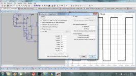
You can change the generator rise and fall times.
Attachments
In principle such a computation is made without the input high frequency
attenuation capacitor and without output LR filter, this to check if the amp
is unconditionaly stable.
Indeed , most amps rely on theses filters to be stable as conditionnaly
stables amps allow to reduce THD by the virtue of greater HF loop gain.
attenuation capacitor and without output LR filter, this to check if the amp
is unconditionaly stable.
Indeed , most amps rely on theses filters to be stable as conditionnaly
stables amps allow to reduce THD by the virtue of greater HF loop gain.
In principle such a computation is made without the input high frequency
attenuation capacitor and without output LR filter, this to check if the amp
is unconditionaly stable.
Indeed , most amps rely on theses filters to be stable as conditionnaly
stables amps allow to reduce THD by the virtue of greater HF loop gain.
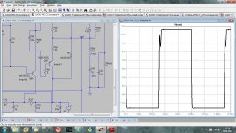
What you suggest to be rise and fall time, 10nsec is to short? If I use 200nsec and remove input filter all is OK.
dado
10ns should be enough , it s about the value of average real world generators.
So far the few sims i made with your amp show a tendency to oscillate
with relatively small capacitive loading , i ll recheck using the models you
did provide with the LT Spice file.
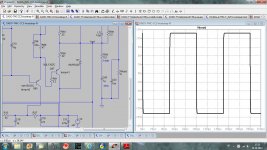
I've got better square wave behaviour with change in LTP CCS, I moved C8 from base-emitter to base- collector (Q1) and set for 150pF.
I am not sure what capacitance value is standard for that kind of test. For big capacitance value there is L//R to protect from oscilation. Already small resistance(0.22ohm) in the output will cancel most of oscilation. JLH used that in his 80W mosfet amp.
In principle such a computation is made without the input high frequency
attenuation capacitor and without output LR filter, this to check if the amp
is unconditionaly stable.
Indeed , most amps rely on theses filters to be stable as conditionnaly
stables amps allow to reduce THD by the virtue of greater HF loop gain.
What do you mean (analytically) by "unconditionally stable" and "conditionally stable"?
I don't think the input filter has much to do with the overall stability (in the small signal sense, OLG, etc...). Some large signal effects may happen during very fast transients, but these are beyond the scope of the current discussion.
The output filter effect on stability is relevant only in the context of reactive loads.
This amp, of course, is not unconditionally stable. It is not stable at the gain of one, as this is not an opamp it is not needed to be. It is design to work with the gain of 28 dB with good gain margin, and it is very stable, but I like to hear different opinion and suggestion how to test it, and to improve it.
dado
If we accept this definition of "unconditionally stable" (an amp stable at any closed loop gain), then a "conditionally stable amp" like yours will always have some pulse response overshoot (such a "conditionally stable" amp is necessary an at least second degree underdamped system - see the phase response with a dip before ULG, this phase dip is what creates instabilities at e.g. low CLG). This overshoot can be tamed using an input filter, but then it is not realistic to expect, in simulation or practice, perfect step response without one.
- Status
- This old topic is closed. If you want to reopen this topic, contact a moderator using the "Report Post" button.
- Home
- Amplifiers
- Solid State
- Little GEM