still4given said:I suppose if you run the Super A in A/B mode then it would. PMI sent me an email with values for parts that will allow it to run at higher voltages but I think the current is still limited to A/B operation.
Super A is Class AB, it is simply biased higher than most others.
AndrewT said:In all the above experiments you will find a significant improvement in PSRR if the low level stages are supplied with a ripple free supply, either a good regulator, or a good cap multiplier.
The improvement is so good that it supports the philosophy of builders of plain ordinary supplies for the output stage and only consider regulation for the voltage amplifier stages.
Are there are special considerations when adapting an existing circuit design to operate the IPS and VAS stages from a seperate, regulated supply, while the OPS continues to use simple bulk cap filtering?
Is it as simple as splitting the two rails and hooking the newly formed IPS/VAS rails into a regulated source? What is the consequence of the potential difference between the IPS/VAS and OPS rails? What does the grounding scheme look like?
If the improvement is as dramatic as you say (I don't doubt) then why don't we see more power amp supply boards with a low current regulated supply section. It would take up very little board space - an LM317 & 337, a few diodes and small passive components.
AndrewT said:I generally take quite a long time to research my projects.
You seem to be very different in outlook.
The world might end tomorrow, let's bash on, there is no time to do any research. Damn the consequences.
I enjoy spending time researching topics of interest. I also enjoy spending time in the workshop building things: drilling, soldering, wiring (or working on cars, etc). Sometimes I spend a lot of time researching a design and never build it. Other times I'm in the mood to build something and those times investigating every last detail would detract from the enjoyment. You might regard that as impatience; I would disagree. I don't mind making mistakes, to me that is part of the experience.
Last edited:
...
Hi dudaindc,
I wish I had known about those. I have already ordered some from Ebay. Where are you located? It could take weeks for the others to arrive. I may opt to buy some from you as well.
Thanks, Terry
Hi Terry,
I am in the metro Washington DC area.
Please drop me a PM if you need anything.
Caps could be in your hands in 3 days via Priority Mail.

Cheers,
D
Heatsinks are good dear Terry
Voltage drop..... practical way without worry about what is voltage drop:
Take you multimeter and set it to read 20 volts DC or something alike..more than 10 volts.
One multimeter probe point goes to the series pass transistor colector
The other goes to the series pass transistor emitter
Adjust the rail trimpot to read 5 volts..... ready!
Do the same to the other rail, measuring other rail transistors and adjusting the other trimpot.
regards,
Carlos
This regulator was made for you to save some money
because electrolitic capacitors are expensive.
This amplifier, when operating 2 ohms, and using the standard supply (rectifier and filters) will need 60 thousand plus 60 thousand microfarads.. this means you may need to use 24 capacitors of 5000uF.. the ones you can have by lower price.
Was the solution, as the standard price of capacitors use to be high...exception are the ones Duda found in Ebay and because of the low price he bougth a huge stock.
When you drive your power amplifier hard, draining huge current from your supply (full power at 2 ohms) the mains frequency or twice the mains frequency appear in the sound reproduction.... the way we have to be rid of that is capacitance multiplier or other kind of electronic filter.... to allow you to filter using much less capacitors.
You see that 24 capacitors uses a lot of space, or needs room to be installed...the electronic supply can be even smaller if you install vertical heatsinks in a blade style, this may save some internal space and the performance is better than single capacitors filtering...voltage is much more stable and mains noise is smaller.
Another advantage is that you will be rid of the current surge that happens when you switch the power on into a supply that uses 60 thousand plus 60 thousand microfarads..sometimes the current is so big that can burn your fuses...then you will have to use a current surge protection circuit...this creates one more pcboard, more circuit, relays, transistors and several other passive parts (see Rodd Elliot surge protection).
regards,
Carlos
Because of some high power amplifiers .....
Zimmer is working hard in a research to develop a SMPS good enough to feed high power amplifiers.
He is facing problems, as to provide kits, and pcboards, the stuff gonna be heavy (transformers, special heatsinks) and big in size.
Another big problem is that we cannot provide instructions for people to make the transformers themselves..... this ask for a lot of special skills, it is complicated and sometimes critical.... mistakes produces expensive parts fried.
Zimmer have already spent a lot of money doing it, several prototypes made....now a days things are becoming a little bit better.
We are trying to find solutions because some future amplifiers, as Dx Boom, Apocalypto, Troyan, DHR Turbo, Armagedon and MAKO demand huge supplies and the transformers will be so big that you will have troubles to handle... we are needing something smaller and lighweigth.
I personally do not appreciate SMPS, because of RFI or magnetic interference it generates that forces you to filter into the power amplifier reducing the bandwidth .... another solution is to shield into a magnetic case.... another thing i dislike is the speed to supply energy...we cannot use 20 thousand plus 20 thousand microfarads in the SMPS output because the current surge will make it shut down..... but we are searching for solutions.... Zimmer is burning fingers and i am helping a little, as i am not skilled about the stuff.
Another problems is that SMPS uses mains voltage rectified...this is dangerous..some beginners have the audacity to try themselves when they should be distant from the mains wires.
We cannot offer pcboards and schematics...people will not build the transformers....so..... we have several things to figure out a good solution.
In the reality we are in a big trouble... we need something like that because of high power amplifiers...we are not skilled... and we do not want to copy other supplies... we want to develop our...if gonna be alike or not this does not matter.....what matters is for us to know we are doing ourselves.
Maybe we will be forced to accept some voltage drop...or something not perfect into our point of view... we may have to say:
- it is quite good, not perfect, it is the best we could do
So, we may have to make concessions as we do not have all the needed skills to make a perfect one.
Well..... who knows?....maybe we will figure out the needed solutions.... this is what drive us.
regards,
Carlos
Attachments
Last edited:
...
Was the solution, as the standard price of capacitors use to be high...exception are the ones Duda found in Ebay and because of the low price he bougth a huge stock.
...
Carlos, just for clarification I would offer the following.
The capacitors I am selling were NOT purchased on eBay, and were not purchased by me.
They were purchased in a large quantity by the company of a friend of mine through an authorized distributor.
These were intended for a project that was ultimately cancelled by my friend's customer before filing for Chapter 11.
These are being sold here and on eBay as I am trying (as best as I can) to help my friend to recover part of the money lost on this project.
I purchased a box (200 units) for myself and sold about 34 boxes so far. I believe he has about 15-20 boxes left.
One would have to purchased 10,000 units in order to pay the price asked for a single capacitor, so these are a good deal IMHO.
Back to the thread...
Cheers!
I am sorry....i may have offered a wrongidea about you.
regards,
Carlos
No problem at all Carlos.
I just want to avoid confusing my caps with fakes from eBay.
The first post on both threads (see my signature) tell a little about the origin of the caps.
Those are really nice looking boards...
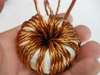
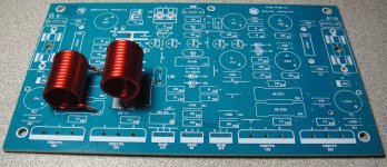
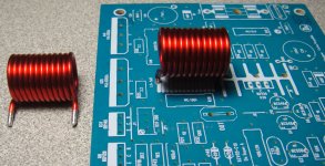
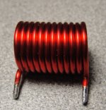
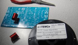
Hello guys today I just got a copper enameled
wire I chose 15 AWG gauge and if fits nicely here
are some images this is my second board that
I have parts on order for this second
channel,
so max wire diameter is 15 AWG
Regards
Juan
wire I chose 15 AWG gauge and if fits nicely here
are some images this is my second board that
I have parts on order for this second
channel,
so max wire diameter is 15 AWG
Regards
Juan
Attachments
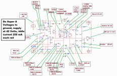
I am not posting voltage chart anymore...will explain why
but will do that for you as you are asking.
Why not this does not help?
Because when we have something assembled wrong way, almost all voltages get strange.....not only the mistake site looks strange..so...this does not inform where is the mistake.... if the guy is skilled in electronic analisis, he will spend third times the space of time required to detect a BD139 inverted (for instance).
The voltage debugging shows a tragedy, several voltages strange.... a caotic image that helps no one.
What help is to check each part, to measure each part, to paint red each part checked (in the schematic or the real component).
I do think it is a waste of time...your time and my time...but i will give my time for you gladly..will produce the chart now.
regards,
Carlos
Sorry, I thought that since you have a spice model, producing a chart might be easy. I am not skilled in electronics but can read a DMM. I have slaved over the boards with an ohm meter looking for where the problem is but just can't find it. I hoped that seeing the proper voltages would help me track it down. I have caused wear on my MKIII boards because of many part replacements. I don't want to do the same to these. I tried to be very careful with part selection, measuring each part before installation. If it is too much work, please don't bother. I have other amps to build. I can set this aside with the MKIII until I have more knowledge and can figure it out. I know you are busy designing new amps.
Blessings, Terry
Blessings, Terry
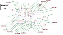
Well...you deserve one hour of hard work to uncle charlie
sadly i do think this will not help you....well....maybe....who knows?
Check in advance the transistor pin...go to google datasheet and check BD139/140 pin identification.... this is confused, as we have some that has metal exposed and others that have not..so... reference of position is strange.
Amplifier was deeply tested...pcboards was assembled many times..there's no errors..... the mistake is obviously something made when you have assembled, so, it is solder, or lack of jumper, or bad solder, or not soldered, or parts inverted, or parts wrong way installed..or missed parts, or supply voltage inverted...it is always our human mistakes ( i use to make mistakes daily..if something can be inverted..then uncle charlie inverts)
Voltage chart will increase panic...this is what i think.....you need to clean your glasses, install good light, sit confortably, watching schematic you must check each value with multimeter...watching parts in the board..painting red into the printed schematic what you have checked.....it is hard work.... takes time...but we always find the mistake this ancient way to track things...paint parts into the schematic...checked parts painted..then all painted..all checked...not working?... then it is the supply voltage or the speaker or the audio source or your multimeters.
regards,
Carlos
Attachments
When i assemble....two things happens....
Do not work and do not operate....always i make some sheet (paper).. this is my standard.
What i do not use to do is to tell people about my mistakes..because they will realise.
- If uncle charlie, old and skilled, make mistakes... things does not work first time.. of course i will face troubles too!
So, i do not let them thinking this way not to have them to loose courage to face the challenge to build by themselves.... i go burning my fingers and exploding things but i only publish glories and sucessfull moments.
This is my behavior...i am terrible! ..... my brain has half of the space filled with air, the other half is a lonely last neuronium tired.
You are not worse than me....difference is that i do not show my multiple mistakes.... picture is me...not you!
regards,
Carlos
Attachments

Last edited:
Interesting Dubai...i do love you too
We are even Dubai!
Warm regards,
Carlos
.........................................................................................................
I am confused.....Terry asked voltage chart to Dx Super A or for the MKIII?
We are even Dubai!
Warm regards,
Carlos
.........................................................................................................
I am confused.....Terry asked voltage chart to Dx Super A or for the MKIII?
Last edited:
ahehehe...i love you uncle charlie.....
Willie !!! what up man good to see you here man
Carlos is something jejejejeje Regards
Juan
Willie !!! what up man good to see you here man
Regards
Juan
Thanks dear Juan... i'm always around in DX thread and i'm really having fun reading just like my favorite electronics book....
hehehehe...Regards,
Willy
- Home
- Amplifiers
- Solid State
- Dx Blame ST together Dx Super A