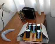
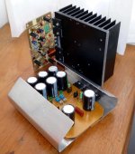
Here you have some more...but all mine own prototypes
I really work hard...when i see the many times i have assembled for test purposes i can see how obsessive i am to check the stuff.
My god....i see i am a little bit sick!
The one with wooden base, the MDF with dark brown cover surface, is good in size to feed two channels at 2 ohms...half of that size to 4 ohms and 1/4 of that size to 8 ohms.
But this is when you have 5 volts from colector to emitter...if voltage is different than that (input voltage), then the heatsink demand increase a lot.
The biggest one was tested with 65 volts in the input...but you see that is too much big...this way, with wrong voltage in the input, you gonna need a dedicated enclosure to the power supply...an overkill.
We are developing a Switching Power Supply....it gonna be available after December (I hope) when we gonna release the Armagedon..then the size will reduce.
SMPS is a problem...we are trying to shield and to filter the way we need..also to increase frequency in order to avoid the amplifier to be interfered by the oscilator frequency.... i hope we suceed...but this is a big challenge for us.
regards,
Carlos
Attachments
Hi, Juan. Are you using DesignSpark?
That is Google Sketch up using millimeters measurements
")
Regards
Juan
That is Google Sketch up using millimeters measurements
Regards
Juan
Thanks. Nice job.
Now i realise that people have not sent me images
or.... i have deleted them all...or the 100 pcboards sold was not assembled (Dx Supply).... i do not have pictures.....i am asking Zimmer.
Cell phones..... maybe this is the reason...i use to ask them high resolution images....as people cannot do this..then they do not send images.
Only some high end cell phones can do it..... even Iphone4 cannot do it.... images from cell phones use to tbe terrible.
I am sorry Terry... i know that without watching you will feel not safe....i understand as this happens with me too.... we share the same way to see things... we believe in what we see.
But, if you want to "believe"...then 15 by 12 centimeters (aproximatelly), one aluminum blade to each rail, will fit... this is a 25 watt heatsink if installed in vertical position having ventilation holes below the aluminum blade and ventilation holes above the ventilation holes.... i have tested and performed very well..... i am adjusting 5 volts from colector to emitter...under such condition it works fine and my environment average temperature is 28 degrées celsius...... aluminum reach 40 degreés when i drive the audio amplifiers hard with music at 2 ohms and continuous tone at 4 ohms loads.
regards,
Carlos
Last edited:
I am thinking about using two heatsinks like I used on my X-BosoZ preamp. They have a 115mm x 35mm x 7mm plate with 10 each 50mm x 35mm x 3mm fins. You can see them here.
Do you feel those may be enough?
Also, I asked in the wrong thread. Can Q39 be mounted on the main heatsink and just fly the wires back to the PCB?
Thanks, Terry

Do you feel those may be enough?
Also, I asked in the wrong thread. Can Q39 be mounted on the main heatsink and just fly the wires back to the PCB?
Thanks, Terry
No, they are small....you can use your aluminum enclosure
As heatsink...install pcboards in the sides..internally naturally, and use a fan blower inside or outside the case to suck air from the internal to external.
To do that you must open holes with your drill bits down the heatsink to force an air current or convection too...also holes upper the case or heatsink.
This heatsink i can see is really small..not good to 8 ohms and one channel.... many times no good for one channel at 4 ohms and extreme small to operate 2 ohms.
Attach this one and other one if you have, outside the aluminum case, as side heatsinks..external side heatsinks..and use thermal grease where you join them with the aluminum enclosure..the same way you use white (yellow in states) wooden glue to attach wooden panels.
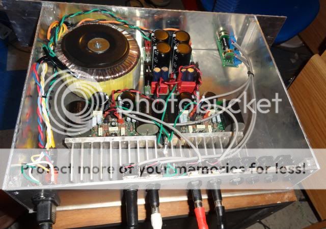
With a fan blower sucking air.... with power transistors at the enclosure sides..with holes down the power transistors and up the power transistor..and with the heatsink or heatsinks externally, then you may face your transformer power.... the 500 watts transformer can put out maybe 350 watts rms of audio.... 180 to each channel aproximatelly.
Man!..you imagine a strong amplifier.....you gonna felt down from your chair...this machine is really powerfull.
If not result powerfull, then come to me and we gonna adjust the gain resistor for you to produce an earthquake in your home.
regards,
Carlos
As heatsink...install pcboards in the sides..internally naturally, and use a fan blower inside or outside the case to suck air from the internal to external.
To do that you must open holes with your drill bits down the heatsink to force an air current or convection too...also holes upper the case or heatsink.
This heatsink i can see is really small..not good to 8 ohms and one channel.... many times no good for one channel at 4 ohms and extreme small to operate 2 ohms.
Attach this one and other one if you have, outside the aluminum case, as side heatsinks..external side heatsinks..and use thermal grease where you join them with the aluminum enclosure..the same way you use white (yellow in states) wooden glue to attach wooden panels.
With a fan blower sucking air.... with power transistors at the enclosure sides..with holes down the power transistors and up the power transistor..and with the heatsink or heatsinks externally, then you may face your transformer power.... the 500 watts transformer can put out maybe 350 watts rms of audio.... 180 to each channel aproximatelly.
Man!..you imagine a strong amplifier.....you gonna felt down from your chair...this machine is really powerfull.
If not result powerfull, then come to me and we gonna adjust the gain resistor for you to produce an earthquake in your home.
regards,
Carlos
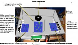
Here you have an idea Terry...but you should do it your own way
This is what give us pleasure..to create our own stuff.
Nice place Terry!
http://www.youtube.com/watch?v=-3QRxpr3tAI
regards
Carlos
This is what give us pleasure..to create our own stuff.
Nice place Terry!
http://www.youtube.com/watch?v=-3QRxpr3tAI
regards
Carlos
Attachments
Last edited:
Hi Carlos,
I may have confused the issue. What I am talking about is heatsinks for my power supply, not the amp. Here is a picture of the heatsinks beside the PSU PCB. If you are saying these are still too small I will come up with another solution. I do not want a fan running.
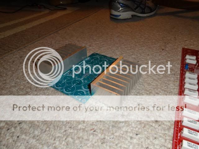
Thanks, Terry
I may have confused the issue. What I am talking about is heatsinks for my power supply, not the amp. Here is a picture of the heatsinks beside the PSU PCB. If you are saying these are still too small I will come up with another solution. I do not want a fan running.

Thanks, Terry
Terry, what voltage drop will the regulator need to cope with (i.e. Vin - Vout) and what is the lowest output impedance that the amplifiers will need to handle (this determines peak current). I think your heatsinks will be fine unless you're planning on driving big loads (<4R) or large voltage drop (>5VDC).
There in lies my problem. I have no idea what is meant by "voltage drop". I had the same problem with the Mr Evil Capacitance Multiplier. I don't understand the whole idea of voltage drop, what it accomplishes or why it is necessary. The whole concept confuses me.
I see pictures of guys with a single sheet of aluminum as a heatsink and they say it works. I may just go with what I know and use a CRC supply. The whole idea of wasting power into a heatsink before it even gets to amp makes no sense to me.
Thanks, Terry
I see pictures of guys with a single sheet of aluminum as a heatsink and they say it works. I may just go with what I know and use a CRC supply. The whole idea of wasting power into a heatsink before it even gets to amp makes no sense to me.
Thanks, Terry
The voltage drop over the power supply transistors, is simply
the (transformer a.c. voltage divided 0.707) minus (the dc output voltage of the regulated supply) .
Let's say you want 28V dc per rail and have a 25Vac-0-25Vac transformer.
Drop = (25 / 0.707) - 28 = 7.3V not taking into account other losses to keep it simple.
the (transformer a.c. voltage divided 0.707) minus (the dc output voltage of the regulated supply) .
Let's say you want 28V dc per rail and have a 25Vac-0-25Vac transformer.
Drop = (25 / 0.707) - 28 = 7.3V not taking into account other losses to keep it simple.
The reason is that you end up with much less ripple, which in turn gives better sound quality.
Terry, have you looked through the capacitance multiplier thread? PMI has a running group buy for boards, which I have built for VSSA. It gives some of the benefits of a regulated supply without some of the disadvantages. I think you'd like it and would work well with SUPER A.
Terry, have you looked through the capacitance multiplier thread? PMI has a running group buy for boards, which I have built for VSSA. It gives some of the benefits of a regulated supply without some of the disadvantages. I think you'd like it and would work well with SUPER A.
Last edited:
Still4, you are basically right.That is my dilemma. If you want 28V rails, why wouldn't you just start with a 20vAC transformer? Why waste off power into a heatsink when it can be used to play music? You are going to lose enough to the heatsinks in the amp.
A power amplifier has very little to gain in using regulated power for the output stage. And this gain is only available if the regulated high current supply is designed to complement the power amplifier. They must be designed as a pair.
The front end that generally consumes just tens of milliamps can gain a lot from using a regulated supply. The potential gains are reduced noise, reduced interference, reduced hum.
Need caps?
Terry,
These are among the options that would work just fine.
Carlos used them during prototyping.
http://www.diyaudio.com/forums/swap-meet/184977-rubycon-4700uf-x-63v-rohs-1-25-each.html
http://www.diyaudio.com/forums/swap-meet/212494-nichicon-4-700uf-x-63v-1-25-x-25-a.html
Hi Crispy,
Naw, it won't work, the lead spacing is actually ok, it's the diameter of the cases that is the problem. You can see in the attached picture. They overlap everything. Best to just buy some new caps. Found some on ebay for less than $20 for a whole set of 4700/63v.
Terry,
These are among the options that would work just fine.
Carlos used them during prototyping.
http://www.diyaudio.com/forums/swap-meet/184977-rubycon-4700uf-x-63v-rohs-1-25-each.html
http://www.diyaudio.com/forums/swap-meet/212494-nichicon-4-700uf-x-63v-1-25-x-25-a.html
Last edited:
Hello Junie
You asked me to post a picture of the chassis layout that I had in mind.... well here it is.
Regards
I apologize mister Ranchu32 I didn't have the chance to make your designs illustration I was really busy with the orders but I will make it
Regards
Juan
The reason is that you end up with much less ripple, which in turn gives better sound quality.
Terry, have you looked through the capacitance multiplier thread? PMI has a running group buy for boards, which I have built for VSSA. It gives some of the benefits of a regulated supply without some of the disadvantages. I think you'd like it and would work well with SUPER A.
Hi Ranchu,
If you look through that thread you will see that I have already built two of those. I had planned to build the VSSA and Peeceebee. The problem is that they can't take the current needed for class A. Someone is working on a solution but I have been told that as is, it won't work. I suppose if you run the Super A in A/B mode then it would. PMI sent me an email with values for parts that will allow it to run at higher voltages but I think the current is still limited to A/B operation.
Andrew,
Thanks for the explanation. So is the belief that more voltage drop = less ripple? How is this measured so you would know when you have reached the optimum?
Hi dudaindc,
I wish I had known about those. I have already ordered some from Ebay. Where are you located? It could take weeks for the others to arrive. I may opt to buy some from you as well.
Thanks, Terry
Still4,
if your handheld DMM will tolerate high Vdc when set to low Vac ranges, you can use your DMM.
Clip your DMM set to 200Vdc across the smoothing capacitor.
It will read the average voltage between the pins.
That average voltage will vary from part cycle to part cycle.
The time for 1 whole cycle at 60Hz is ~ 16.7milliseconds.
The DMM takes many samples of that varying voltage and averages them to display on your screen.
Now switch to 200Vac. The meter reads the instantaneous voltage and reads off the changes to arrive at an AC voltage. It then takes many samples and averages the Vac. It scales the average to match what the RMS of a sinewave would have been for that average. The approximation that is displayed is usually <<1.000Vac.
If it is that low, then change to 20Vac. Is the reading <<1Vac? Then switch to 2Vac.
Is the reading <<100mVac? If so, then it shows that the DMM is substantially ignoring the Vdc that is superimposed on the ripple. It is now safe to select the 200.0mVac scale.
What is the reading?
Multiply that scaled rms equivalent reading by 3. The answer is an approximation to the ripple voltage in Vpp.
When the PSU is not supplying current to the amplifier (disconnected) the ripple will be ~1mVpp
When the amplifier is connected and drawing quiescent current the ripple is likely to be ~10mVpp
This is the ripple that must be canceled by the output stages PSRR to be able to hear no hum <~0.9mVpp (or <~0.3mVac).
If you add on a second DC load to that supply, the ripple will increase. You can measure whether your amplifier now hums, or still manages to ignore small ripple values on the supply rails. If you connected a very high current DC load to the PSU your are likely to hear a very pronounced hum That is because the PSRR of the amplifier is limited. PSSR is not infinite. Eventually some of the rail ripple gets through as audible hum.
This is an experiment that is worth doing to hear the effect of limited PSRR of an amplifier.
It is where a ClassA amplifier falls down. There is very high ripple on the supplies due to the very high current demand when in the quiescent state. Hum comes through when the music is off, or very quiet. It is the main reason that high values of smoothing capacitance are used in ClassA and why rCRC or rCLC PSUs are adopted.
In all the above experiments you will find a significant improvement in PSRR if the low level stages are supplied with a ripple free supply, either a good regulator, or a good cap multiplier.
The improvement is so good that it supports the philosophy of builders of plain ordinary supplies for the output stage and only consider regulation for the voltage amplifier stages.
I generally take quite a long time to research my projects.............I wish I had known about those. I have already ordered some from Ebay. Where are you located? It could take weeks for the others to arrive. I may opt to buy some from you as well.........
You seem to be very different in outlook.
The world might end tomorrow, let's bash on, there is no time to do any research. Damn the consequences.
- Home
- Amplifiers
- Solid State
- Dx Blame ST together Dx Super A