Dear Terry, your transformer can "produce" 350 watts RMS of sound
So, it will be good to power two channels of the Dx Super A operating at 8 and also 4 ohms.
In the reality your will have to adjust your Dx Supply to 35 volts to keep some volts available to the regulator to do it's job... this way your output power gonna be 50 plus 50 watts RMS at 8 ohms.... 100 plus 100 watts RMS at 4 ohms and will be able to put out 160 plus 160 watts RMS at 2 ohms.
Your heatsink must be bought to dissipate 250 watts each one of them.... i do think in the internet you can buy heatsinks using the watts as data to enter..if not, then ask a forum friend to help you.
I am a Broadcasting Television Professional, and a Psychologist as a degrée (never used...just a paper to decorate wall)...i also do not understand about heatsinks.
I have developed a method.... and this is easy to understand:
A squared blade of aluminum, 4 inches size to each side, 1 to 1.5 milimeters thick, is good to an amplifier putting out 10 watts RMS of audio.
So, 2 blades (fins) will be good to 20 watts
So, 3 blades (fins) will be good to 30 watts
this way you can evaluate the heatsinks you have...based into dimensions.... convert into area multiplying side by side and make your calculations
Each amplifier channel, will need 16 of these blades to continuous power.... a half of that for music...but if you push it hard at 2 ohms...if you gonna use 4 and 8 ohms...these heatsinks you see inside mini audio systems will fit..these ones you see attached to STK audio amplifier modules..count the fins and evaluate...this is all i can do to help you.
No problem to make mistakes...if you decide for a really big heatsink..much bigger than the size you need..the result will be your amplifier operating cool...if you decide for an unit smaller than the needed size, then it gonna be too much hot and you will attach a fan to help the cooling...just that.
regards,
Carlos
Last edited:
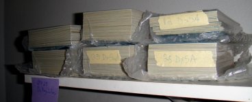
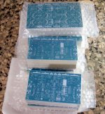
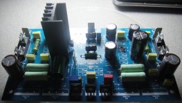
Wow, OK, so I sent payment at 3PM on Saturday and the boards arrived today. Simply amazing. Nice boards too. So much for me gathering the parts while I waited for the boards. 
Only one bummer, the PS caps that I was hoping to use don't fit. The caps I have are 35mm and the board needs 25mm. Not a huge deal but there are twelve of them. Looking on ebay right now. I already completed my order from Mouser. That should be here any day.
Thanks Juan for being so prompt!
Blessings, Terry
Hello guys
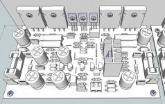
well I like to share my ideas as always I was simulating how the final project looks like using Google Sketch
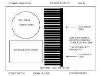
Hi Juan, I really like the way you have mounted both amplifiers (stereo pair) on a single heatsink. I will be building my DX SuperA with single heatsink in the middle of the case seperating the transformer and regulator board.
In my opinion this makes for a "cleaner" looking case (no heatsinks visible on the sides or back of case).
Wow, OK, so I sent payment at 3PM on Saturday and the boards arrived today. Simply amazing. Nice boards too. So much for me gathering the parts while I waited for the boards.
Only one bummer, the PS caps that I was hoping to use don't fit. The caps I have are 35mm and the board needs 25mm. Not a huge deal but there are twelve of them. Looking on ebay right now. I already completed my order from Mouser. That should be here any day.
Thanks Juan for being so prompt!
Blessings, Terry
I'm happy for you mister Terry you did get the boards fast wow !
Regards
Juan
Hi Juan, I really like the way you have mounted both amplifiers (stereo pair) on a single heatsink. I will be building my DX SuperA with single heatsink in the middle of the case seperating the transformer and regulator board.
In my opinion this makes for a "cleaner" looking case (no heatsinks visible on the sides or back of case).
can you make a quick drawing of your idea if possible ?
Regards
Juan
Terry see if you can drill new hole for your caps to fit. Usually excess traces on filter cap are adaptable to different size caps...
Hi Crispy,
Naw, it won't work, the lead spacing is actually ok, it's the diameter of the cases that is the problem. You can see in the attached picture. They overlap everything. Best to just buy some new caps. Found some on ebay for less than $20 for a whole set of 4700/63v.
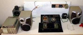
I was surprised. I had almost all of the resistors and diodes that I needed. Only a couple values lacking. They will be here sometime this week. I just needed to feel the heat of the soldering iron.
I have all the transistors already, I'm just waiting on a few resistors and some caps and I can finish it up. I always like to install all the resistors and diodes first so I can use the table to keep things tight. If I can decide on some heat sinks, I should have it playing music by the weekend.


can you make a quick drawing of your idea if possible ?
Regards
Juan
Its like the drawing I posted a few pages back in this same thread:
An externally hosted image should be here but it was not working when we last tested it.
Juan, I will upload a better drawing tonight.
I sent you an email yesterday to get your paypal details and shipping costs for the boards I wanted.
Another Australian member has contacted me who is also interested in a set of boards. Can you tell me:
a) Do you have another set of boards available
b) What would be the combined shipping cost for 6 boards (4x amplifier, 2x regulator) in the one package?
Terry, do not forget the power transistor insulators
Some tips:
Use thermal grease too... attach transistor applying some strenght... a lot of heat is generated there as transistors are resistors.... they are variable resistors, or transference resistors....where we have resistance we gonna have heat.
To clean the excess of grease use cotton wabs (cotonette from Johnson and Johnson) dampened with Kerozene.... clean also using a cloth dampened with Kerozene...but do not use too much liquid into the cloth or the cotton, because if liquid, it infiltrates behind the transistor and dissolves the grease..so....humid, not wet.
I am glad you have received your pcboards so soon...... this is very good.
Carefull with the polarity.... check cables before you power the unit on..... the circuit may have series protective resistors and fuse holders...remove the fuses to adjust the bias current...it can be the standard 250 mA or if you want can be 60 mA (only class AB even to small power) if you face troubles with your heatsink size.
This amplifier can operate with 1mA of bias till 500 mA...the lowest the current, the less gonna be the stand by heat and also the dinamic heat.
I am old and i use to put transistors in wrong place..even when there are indications printed into the pcboard..... so....as this is possible and i do it every day, check it twice before power the amplifier on.
Input cables must be shielded audio cables.... the best we find in Brazil are Philips brand.
If you connect a cheap chinese audio cube you must install 100n (0.001uf) capacitor from live to ground in the input, to drain high frequency from the digital oscilators inside the class D audio amplifier of these audio cubes...cell phone can be used, and these, normally do not need the capacitor...but if you perceive heat in the output zobel capacitor or output zobel resistors, then it is showing you are amplifying high frequencies that comes from the audio source...so, in this case install filter...can be othe value as 47n, 56n, 68n, 82n, 150n and so on..the higher the better but also the treble gonna be killed because of these capacitors draining some high frequencies to the ground.
Attention to avoid shorts while soldering...clean the pcboard with a brush and kerozene and inspect it with lenses, or magnifier.
Before power one measure resistance (2M scale) to see if you have high resistances (bigger than 100K) from positive to ground, negative to ground and positive to negative...do this with supply disconnected to be easier to measure.... adjust and check the supply before you connect it to the power amplifier....be carefull about polarity..... measurements of resistance delays a lot and you gonna have overflow of numbers changing at your sight, this happens because electrolitic capacitors charging and discharging.... invert your measurement probes....take some time checking for human mistakes..this will save your against a lot of frustration and sadness....waste some time checking before you apply power...if you have a small supply.... 12 plus 12 volts or even 20 plus 20 volts.then use it for testing before you apply the big one.
Cannot adjust more than 42 volts!.... BD139 and BD140 transistors may accept in stand by mode..but if you have higher voltage and push the amplifier hard, then they will explode because excess of voltage....limit is 42 and do not go above.
You can use lower voltage from your transformer..but always adjust your supply voltage to have 4 to 5 volts diference from colector to emitter, do not matter what is the voltage..if you probe tips are one into the colector and other into the emitter, the reading must be 5 volts to each one of the rail polarity... positive and negative voltage must be the same..check it and adjust if needed.... not more than 100 milivolts of difference... adjust it till you have the same voltage, or the most matched as possible.
Power supply must be adjusted to have 4 to 5 volts from colector to emitter.... put a black probe tip into the ground and measure positive voltages (positive or negative depending the rail you are measuring) and colector (transistor center lead) must have 4 to 5 volts higher than emitter..be carefull not to produce shorts with your probe tips.
Fuses depends on your speaker impedance....i think i have published something about that...if not, them let me know...you have a fuse value to 8 ohms and higher values of fuses to 4 ohms and even higher to 2 ohms.
You audio quality also depends (a lot) from your speakers....bad speaker will generate bad sound even with excellent amplifiers..... good speakers cannot make magic if the amplifier is no good...so... a good choice of speakers, the home acoustics, your aged years (alike mine) all that contributes to the final result..but i am sure you gonna like it... a lot!
Thanks by the pictures..very kind from you... advertisement helps me to reach my dream ...to have one Dx amplifier in each home.... well... dream is dream....even being an impossible dream.
regards,
Carlos
Last edited:
I was testing if the Super A sounds good with these
speakers.
I found result good.... small bass and strong treble and mids.
This is because the amplifier that matches this speaker have 4 output, four amplifiers, one for bass and other for treble in each one of the 2 channels..so...circuit ballances volume in between bass an treble there.
I have joined the speaker wires together..the bass speaker plus the midrange and tweeter... and no resistor to reduce squawker and tweeter effect..this way resulted too much bright..but quality was very good..unballanced tones but nice quality.
Well, these speaker almost melt...they cannot face the Dx Super A power..... we have twice as much as these speaker can hold.
regards,
Carlos
Attachments
A mistake in post 1014
Here is the original text:
If you connect a cheap chinese audio cube you must install 100n (0.001uf) capacitor from live to ground in the input, to drain high frequency from the digital oscilators inside the class D audio amplifier of these audio cubes...cell phone can be used, and these, normally do not need the capacitor...but if you perceive heat in the output zobel capacitor or output zobel resistors, then it is showing you are amplifying high frequencies that comes from the audio source...so, in this case install filter...can be othe value as 47n, 56n, 68n, 82n, 150n and so on..the higher the better but also the treble gonna be killed because of these capacitors draining some high frequencies to the ground.
....................................................................................................
Here you have the text with correction:
If you connect a cheap chinese audio cube you must install 100n (0.1uF) capacitor from live to ground in the input, to drain high frequency from the digital oscilators inside the class D audio amplifier of these audio cubes...cell phone can be used, and these, normally do not need the capacitor...but if you perceive heat in the output zobel capacitor or output zobel resistors, then it is showing you are amplifying high frequencies that comes from the audio source...so, in this case install filter...can be other value as 47n, 56n, 68n, 82n, and so on..the higher the better but also the treble gonna be killed because of these capacitors draining some high frequencies to the ground.
Thank you Bob Burbeck as you have pointed me the mistake.
regards,
Carlos
Last edited:
Hello guys
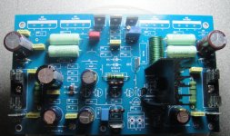
I was comparing my simulation to the real thing it was almost as I thought how will look like and I feel really happy with the results, now that I have a bit more time I can gather the parts I need it, thankfully I have must of all 1/4W resistors and I need to get me the caps, those you see on the board are just to see how they look, the green 7 watts emitter resistors is really not need it but I like to make my boards nice and it feels great I'm not sure if you guys think the same way as me, well I have to separate the resistors and commence installed them today "if" I have time jejejejejeje alright guys take care
Regards
Juan
Attachments
Last edited:
- Home
- Amplifiers
- Solid State
- Dx Blame ST together Dx Super A