Juan, take a look at my ignore list and you will understand why
some guys are there.
Do not bother yourself.... your jumpers are there because of me.
So..... you know what i mean.
My ignore list was publish in this same thread Juan, i have already presented you this gentleman.
heheheheheh")
By the way Juanitto, i have retuned the Dx Blame MKIII Hx.... make the modifications suggested in one of your channels and tell me what you have perceived please.
Carlos
some guys are there.
Do not bother yourself.... your jumpers are there because of me.
So..... you know what i mean.
My ignore list was publish in this same thread Juan, i have already presented you this gentleman.
heheheheheh
By the way Juanitto, i have retuned the Dx Blame MKIII Hx.... make the modifications suggested in one of your channels and tell me what you have perceived please.
Carlos
Last edited:
One more to increase uncle charlie hits in this thread
Last week we had some trolls and i have jumped from 12000 to the today's rate.
This is good, i may go to 16000 thousand soon.... more than good, some folks come to see when thread hits are high and this i have to thank all non welcome visitors as they increase my popularity.
Thank you folks... you are always welcome to help uncle charlie to be readed.
regards,
Carlos
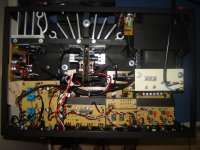
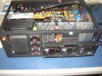
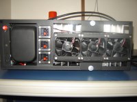
Newton will test and torture the Dx Super A this weekend
He may produce a video and it will be posted.
He will fall off the chair so surprised he will feel to hear the sound of this amp ...... he intends to torture and I think that's great.
As you can see he has all the power he needs to torture..for sure he will not have voltage drop.
regards,
Carlos
He may produce a video and it will be posted.
He will fall off the chair so surprised he will feel to hear the sound of this amp ...... he intends to torture and I think that's great.
As you can see he has all the power he needs to torture..for sure he will not have voltage drop.
regards,
Carlos
Attachments
Last edited:
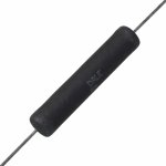
Attention!.... i have made a mistake.
The series protective resistor you may imagine we are using is wrong.... the correct value is 10 ohms and 10 watts...the one we used previously will go in flames because it was not dimensioned to Super A.....cannot face 10 watts each rail.
This way, if you have in your pcboard layout, ignore and remove it, the fuse will bypass making a fuse bridge and install outside the pcboard two big resistors or 10 ohms and 10 watts each one of them..... measure the voltage drop above these resistor extremes (DC volts) and adjust your trimpot to measure 2.5 volts.
After you do that, then your amplifier seems correct and fine as you could adjust..check your off set voltage..if it is less than 25 mV go ahead..if not check for mistakes in your contruction...if it results from 25 mV to 100mV then call uncle charlie.
If you already have adjusted the 2.5 volts and the off set is fine....of course all heatsinks in place, then you check the voltage drop directly above the power emitter resistors (0.22 ohms)..there you should measure 55 milivolts aproximatelly because you are using 4 output pairs and current is shared rail by rail.
regards,
Carlos
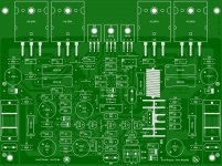
Juan have ordered 10 boards, and have exagerated
in features... copper thickness...colour, solder mask and a lot of things that does not sound but increase the price a lot.
this resulted in 28 USD each...a hell expensive... i told him to sell some pcboards by 18 USD because this was the price paid by the Supercharged boards that had the same size despite not all the features this one has.
He exagerated because passion by his design...matter of fact is that this board is the most beautifull ever done by my people...it is fully symetrical and very well done.
This way.... because we fail to talk about these details, he gonna have some loss of money.
Well...he do not even want to sell them.....hehehehe... passion!
Let it be.
regards,
Carlos
Attachments

Setting 2.5V across a 10r resistor is not 10W.
It is 625mW. A 2W resistor will do this duty in the short time it takes to set the current.
But this is the wrong way to check and set the output bias.
Correct start up and checking procedure.
Start up your project via a bulb tester with a 100r in the fuse holders.
Check that the output bias current is zero amperes.
Measure the voltage across the 100r resistor.
This voltage tells you the current the amplifier is drawing when there is no output bias.
Power down.
Put back the fuse/s. Power up direct off the mains socket.
Measure the Vre voltage. Option: check all the Vre to see if they all read the same.
Adjust the Vbe voltage while repeatedly checking Vre.
Keep increasing till the maplifier has reached about 80% of the Vre you want.
Leave the
Leave the amplifier with no load to heat soak for 30moinutes. Come back and check and reset the Vre to 100% of the value you want.
Leave the amplifier on heatsoak and recheck Vre and output bias every 10minutes. When you are sure the bias and offset are stable and consistent, then you can connect a dummy load. Recheck the bias and offset every 10 minutes over a further hour or two or even three, to be sure you know the amplifier is behaving.
Now switch off and let the amplifier go stone cold.
Start up and check the offset from start up through the warm up phase. Check the Vre.
If you are happy the amplifier does not send a big pulse through the dummy load during start up and warm up, then now is the time to attach a cheap speaker and test with some quiet music.
DO NOT set the Vre with the 10r, or any resistor in the fuse position.
Last edited:
Newton started his tests...he will continue latter on
and this means it is all right... adjustment was easy, off set fine and all stable during the first power up moment.
He had to go out with the family to buy a house to weekend... a small farm to his family, reason why he will continue latter.
He said the amplifier is hot....of course he is talking about temperature because he have not listened yet.... only assembled and adjusted and found that temperature rise to 43 degrées celsius...yes..it is really hot.
In his home the temperature is 27 degrées celsius.... while he is out, a daugther will upload the video showing the adjustment...next will be listening tests.
regards,
Carlos
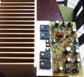
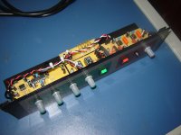
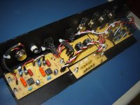
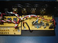
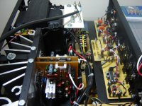
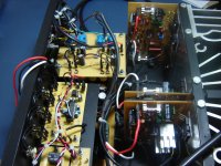
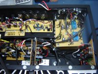
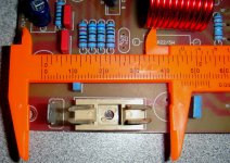
This one is a Blame in process of modification to Dx Super A
You see the fan blowers already in place.
Made in Brazil... this guy repairs automobile
regards,
Carlos
You see the fan blowers already in place.
Made in Brazil... this guy repairs automobile
regards,
Carlos
Attachments
-
 dsc07653j.jpg608.2 KB · Views: 418
 -
 dsc07650e.jpg551.2 KB · Views: 454
 -
 dsc07649f.jpg536.3 KB · Views: 465
 -
 dsc07647xi.jpg548.2 KB · Views: 525
 -
 dsc07664n.jpg581.6 KB · Views: 142
 -
 dsc07662l.jpg595.2 KB · Views: 139
 -
 dsc07660vs.jpg572.3 KB · Views: 157
 -
 dsc07657u.jpg595.4 KB · Views: 160
 -
 dsc07656s.jpg519.3 KB · Views: 163
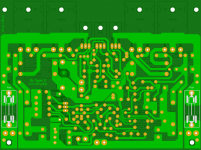
This Dx Super A gonna be alike a torpedo destroying other amplifiers
So, we have decided to make it look agressive.... alike a torpedo boat .... the resistors 10 ohms 10 watts or even 10 ohms 20 watts will look alike torpedo lauchers, they can go above, atop the pcboard and fuzes can be below..these are series protective resistors for adjustment purposes and goes bypassed, or jumped by the fuse after we adjust the stand by current.
As people can choice 250mA, or 500mA and even 1A, then i decide to put huge ones there.
We have stopped the board factory, we gonna make this modification and we gonna order again with some more units for ourselves...instead of 10 will be 14 units for testing procedures... 10 will be sold...will vanish really fast.
A video about....playing with Juan and Zimmer about the stuff:
Ahahahahha! - YouTube
regards,
Carlos
Attachments

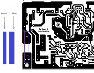

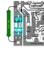
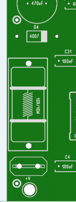
Yes I wish it can be bigger but there is no more room for it, what I did is a representation of the resistor, like a reminder that need a 10R 10W resistor or 5 watt like Carlos said. after the fuse holder is installed the graphical will be hidden so is ok, what I did is add a 2 more holes each side of the board so if the resistor is longer, it can be easily place, there are some brands of resistors that have the length of about 45 mm that can fit to it, I change the silkscreen for the fuse holder and now it will be placed it at the bottom of the board, anyway the fuse FUSE holder drawing is not going to be seen anymore from the top, but now it can be seen from the bottom of the board.
Regards
Juan
Regards
Juan
Attachments
Last edited:
Attention, be aware about the series protective resistor
Here:
Cuidado para não destruir o amplificador - YouTube
Carlos
Here:
Cuidado para não destruir o amplificador - YouTube
Carlos
- Home
- Amplifiers
- Solid State
- Dx Blame ST together Dx Super A