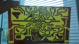
A forum friend sent me private message asking Dx Supply layout
I said that i suppose it was already published as we cannot force people to buy stuff from us.... we have to give them all information needed.
I do imagine it was already posted.....please Juan, point to the guy were is the post with the layout to the Dx Supply to be etched at home.
He said want to make by himself.... cost of shipping to Europe is now a days too much expensive, so, he do not want to order pcboards.
regards,
Carlos
Dear Carlos,
I will use PCB, which are already published in #986 .. I hope, that they are OK..It´s Zimmer design...
Regards,
Marcel
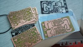
Yes.... pcboards tested.... published layout checked
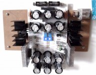
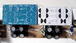
I am using it at home....i have three unit etched at home inside my amplifiers..and the one show is being installed in my workbench.
Workbench unit is to 20 plus 20 watts dissipation only... voltage entering is 40 volts when lightly loaded .... if i adjust it to 36 volts to a modern JLH (for instance) then i will have 8 to 10 watts each rail drained from the supply.
"Input voltage minus output adjusted voltage multiplied by the ampere drained is the power you will be asking from the supply"
Juan Supply pcboard was not assembled because lack of some capacitors in my stock...but it also works fine.
Sorry...pictures distorted because of camera lenses
Be aware about the wire jumpers.... cannot forget these links made with wire..... leads of resistors or telephone wire.... i use to forget them....as a result sometimes things i assemble fails
regards,
Carlos
Attachments
Last edited:
DX Blame SA rivals with high-end hardware!
Dear Carlos!
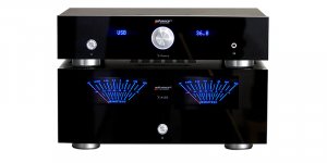
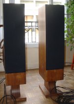
I have spent the day with a friend to compare my DX Blame SA with high-end hardware.
The preamplifier was a "Advance Acoustic X-Preamp" for the listening test and a comparison amplifier "Advance Acoustic X-A160" and the speakers of "Mulidine Space".
DX Blame rivals smoothly with the high-end hardware, can not decide between the two amplifiers. Both amplifiers produce the same sound transparent and detailed.
In summary, the DX Blame SA is a great success!
Regards!
Dear Carlos!
I have spent the day with a friend to compare my DX Blame SA with high-end hardware.
The preamplifier was a "Advance Acoustic X-Preamp" for the listening test and a comparison amplifier "Advance Acoustic X-A160" and the speakers of "Mulidine Space".
DX Blame rivals smoothly with the high-end hardware, can not decide between the two amplifiers. Both amplifiers produce the same sound transparent and detailed.
In summary, the DX Blame SA is a great success!
Regards!
Attachments
It can beat the competition dear Project 16
Because of reliability and difference in gain in parts used, i have decided by a very big compensation capacitor.....when we reduce the value you have clear increase in high end and all harmonics (natural ones) are reproduced..so...bells and whistles appear in your room shinning and reflecting in your walls,
You can reduce..but you must watch a scope and plug audio or generator..better to be generator, 10 watts and square wave...try high frequencies..above 5 kilohertz.... plug and unplug the signal...watch for unstabilities show in the scope....no unstability..then reduce a little bit.
You can go from 220pf to 180pf to 150pf, to 120pf to 100pf, to 82pf, to 68pf to 56 pf and do not go down because for sure you will face problems.
With a multimeter, in AC scale, measuring the output you can also "see" the unstability that gonna appear as AC output..the meter will show some volts...without any signal entering the amplifier.
For the bass you can increase input capacitor and gain capacitor.... go twice and test....also if you decrease emitter resistor, installing other in parallel you gonna have more bass because resistors in series with the signal (the case of the power transistor emitter resistor) kills the bass.
Then you will kick the competition.
Understand that i cannot put that stuff in the schematic..as this is something we have to try in a try and error basis and i cannot offer this as standard..but if you want to take the risk..then tune your to beat all that crap stuff exist around you ...expensive stuff that cannot make music better than it really is in the original..amplifiers can only put out the real recorded sound...magic not allowable, even if they cost 100 thousand US dollar
regards,
Carlos
Reducing the compensation capacitor, the effect is the increase
in high frequencies quality..but there's a limit... if you cross the limit line the amplifier will oscilate...the smaller the better....but also, the smaller the less stable.
So, there's a compromise..... when we make amplifiers to people to assemble, we use two step up (minimum) to have the amplifier very safe, even if the guy change the VAS transistor model or replace with units with different gain and electrode capacitance...so...you have room to tweak and to tune it to be "parfait!"
How you see this...an easy method.
Connect a sinusoidal generator in your amplifier input..then couple a oscilloscope into the output terminal and load the amplifier with speaker or resistor... then start with 10 kilohertz and watch the sinusoidal waveshape in the scope display...then go increasing the frequency..you will see that with 220pf the waveform becomes a triangle at 40 kilohertz..and that if you install 68 pf you can go to 80 kilohertz without distortion....in this case is the waveform shape distortion that produces the audible distortion, as triangle wave sounds different from sinusoidal wave.
Yes...for sure you may say....but i can listen 16 thousand or 18 thousand maximum... so... do not make sense to worry about so high frequencies..... but you can listen the harmonics...and the sound becomes harshing, different, looks to be another instrument.... also the level (volume) of high frequencies are modified and a lot.
So, it is not a matter of audio purity, is also a matter of ballance of tones..the level of treble..the volume into the high frequencies
regards,
Carlos
Last edited:
Very nice work...also excellent pictures..great photo machine you have.
regards,
Carlos
Thank you Carlos..BTW pictures are´s made by my phone
")
I´ll try to do some measurements..but it's take some time to assemble, and I have to try to order output trans....
Cell phone
It´s LG G2. I am very happy with it. I have also digital SLR camera, but phone you have still with you.. Sometimes can take good picture...but, as we know, picture doesn't make camera, but photographer..
some samples...
It´s LG G2. I am very happy with it. I have also digital SLR camera, but phone you have still with you.. Sometimes can take good picture...but, as we know, picture doesn't make camera, but photographer..
some samples...
Attachments


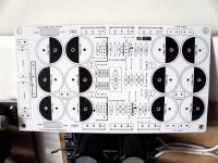
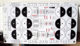
Looks very nice Carlos,have you posted somewhere the schematic or the pcb?Dx Supply installed into my workbench vertical panel...out of the way not to bother my work into the horizontal flat table top... it has voltage adjustment from plus and minus 12 volts to plus 48 and minus 48 volts (5A+5A)...it is adjustable as you already understood, stabilized within 1 percent with electronic filtering (capacitance multiplier effect) to supression of ripple.
Not finished to run cables..i am thinking to run cables from behind the vertical panel...not decided yet.
regards,
Carlos
I didn't followed daily the topic but i am looking for some time to build such a power supply for test.
Have a nice day.
I do think was posted in this same thread.
If not, then try the Power Supply forum.
I am old, i cannot remember...i do think it may be in both foruns... this is what makes sense to me..because the supply was made to play together the Dx Super A...so..the place is this one...also it is a Power Supply..and the place will be the Power Supply forum..... i do think i should have posted in both of them.
Yes...i have checked..it is there:
http://www.diyaudio.com/forums/powe...utput-adjustable-stabilized-power-supply.html
Layout you should search for Juan Vargas if not posted.
regards,
Carlos
Complicated to answer you Bagus...it all depends your supply
Your speaker impedance...in other words...answer is NO and it is YES....it depends.
2N3055 and 2N2955 is weak to now a days standards...it all depends your input voltage, your output voltage and the current...well.... i can write a book of 1000 pages about that...anyone can write that book...but it is better you to give us your parameters then i will be able to reduce the text book.
Your question is one of the most difficult questions to answer i have ever had..... because everything is dependable of everything.
Answer is YES, and NO and more or less...cannot be used and can be used..good to be used and awfull to be used...all depends your parameters.
Return to me with transformer power...electrolytic capacitor values...rectifier values...type of power supply, input voltage with no load..... loaded voltage and inform the load used..the speaker you gonna use.....the impedance of that speaker, does it have passive filters inside the speaker case..does it have inductors and capacitors?...how you use to listen your amplifier?...it is loud?.....what are your audio output power transistor
What amplifier model?
Here you see one of my prototypes...and old one....see the mess!
https://www.youtube.com/watch?v=N_snu9CaHKk
regards,
Carlos
Your supply power...i would like to know
How to discover the power.
Install low ohm resistors.... 2 ohms, 3.3 ohms or something alike....many watts of power....but can be only 10 watts if you measure very fast, switching the power supply "on" just for the time needed to read the meter...install two resistors..one from positive to ground and other from negative to ground... after rectification and filtering.
Now connect (better to solder) a DC multimeter to read the voltage into the resistor.... meter leads will go to the resistor leads.
Switch power on and tell me the voltage reading..
Resistor will become red...do it fast...only the time needed to read the DC voltimeter...1 second maximum.
Inform me your voltage and also if you are using two resistors of the same value and what are the resistor values you are using and the measurement if was made in positive to ground or negative to ground or positive to negative and the value of the resistor used as load.
Do not use wire resistance....because when become hot the resistance value changes...increases...use resistor that will not turn red or overheated.
regards,
Carlos
- Home
- Amplifiers
- Solid State
- Dx Blame ST together Dx Super A