How to check an amplifier pcboard
To know, in advance to connect power, if your assemble is correct.
https://www.youtube.com/watch?v=OA02klmMYaA
regards,
Carlos
To know, in advance to connect power, if your assemble is correct.
https://www.youtube.com/watch?v=OA02klmMYaA
regards,
Carlos
Juan Vargas pcboards for Dx Super A assembled, tested and approved!
https://www.youtube.com/watch?v=CEgK4l0MH8k
regards,
Carlos
https://www.youtube.com/watch?v=CEgK4l0MH8k
regards,
Carlos
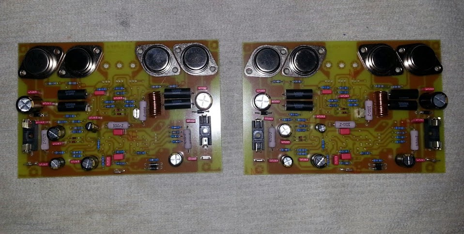
Caps removed
I watch the video and I was amaze that just a simple cap can make a difference wow ? I'm right now heating my hot iron to remove them thanks Carlos")
by the way yes the leads space has to be update on the boards, I thought you will instal them this way as this image but is good that you saw the detail of the copper that is really close to the edge of the PCB "my bad"
ok caps off, sorry I was removing the caps while writing this jejejejeje
Best Regards
Juan
I watch the video and I was amaze that just a simple cap can make a difference wow ? I'm right now heating my hot iron to remove them thanks Carlos
by the way yes the leads space has to be update on the boards, I thought you will instal them this way as this image but is good that you saw the detail of the copper that is really close to the edge of the PCB "my bad"
ok caps off, sorry I was removing the caps while writing this jejejejeje
Best Regards
Juan
Attachments

Greetings,
I am etching boards as I type this for this amplifier. I understand now not to use the capacitor in position C38 - but should it be left empty or are you saying to put a resistor there?
Are there any other modifications that I should be aware of that folks have implemented?
Thank you!
I am etching boards as I type this for this amplifier. I understand now not to use the capacitor in position C38 - but should it be left empty or are you saying to put a resistor there?
Are there any other modifications that I should be aware of that folks have implemented?
Thank you!
You can left it empty
Some guys are not using high current in stand by mode...they are adjusting to 900 milivolts measured in the rail series resistor (10 ohms).
Some guys have small heatsinks and weak supplies....also some of themare not using Dx Supply to save room inside the enclosure and to save money.... these guys (30%) are adjusting to 90mA each rail at iddle.
regards,
Carlos
OK I took willy's TO-3 design and managed to get it to a transparency to make a photo etch board pair. This is the first time using positive pre-sensitized boards and I must say it is vastly superior to the old toner transfer method.
Progress so far...Just need to finish stuffing the boards, just the front end transistors and the jumpers, thats about it. I put the TO-3's in there for the photo op...I love me some TO-3 transistors.
Progress so far...Just need to finish stuffing the boards, just the front end transistors and the jumpers, thats about it. I put the TO-3's in there for the photo op...I love me some TO-3 transistors.
Yes.... a more professional method..much better
toner is to make at home, to amateurs.... and forum is diy.... amateur forum...so...it is nice to the forum.....naturally other processes, more professional ones, results much better.
Congratulations...great job you did.
regards,
Carlos
toner is to make at home, to amateurs.... and forum is diy.... amateur forum...so...it is nice to the forum.....naturally other processes, more professional ones, results much better.
Congratulations...great job you did.
regards,
Carlos
Member
Joined 2009
Paid Member
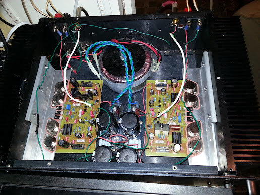
Well I finally got the amp fired up! So farso good...although even at 40v+/- I can only get the bias up to 170mA. I have a 200 ohm pot so iguess I need to adjust the 680 ohm resistor...increase right? I always get that mixed up....
Offset is hovering right around 10mv or less
Anyways the amp sounds really nice and is very quiet.
Here's a pic...still need to clean upmthe rats nest.
Offset is hovering right around 10mv or less
Anyways the amp sounds really nice and is very quiet.
Here's a pic...still need to clean upmthe rats nest.
oh my God ! 10mV offset wow man looks really nice, 40V power supply is ok I'm running the ones I have at 43V, Carlos hasn't seen this yet he will love it!, hey rapid question here, did you use white thermal paste from L shape adapter to the main heat sink ? it looks really clean
About the 680 ohms resistor probably you can lower it to 500 ohms because you are using 40V +/-
the voltage I read from the 10 ohms resistors in place of the fuse on my boards I always adjust them to about 2.5V +/-
Regards
Juan
Regards
Juan
About the 680 ohms resistor probably you can lower it to 500 ohms because you are using 40V +/-
the voltage I read from the 10 ohms resistors in place of the fuse on my boards I always adjust them to about 2.5V +/-
Regards
Juan
Regards
Juan
Attachments
The Vbe multiplier output voltage, or bias voltage, is given by:
Vbe * [Rupper + Rlower] / Rlower
If Rlower is a 680r and a 1k VR, then the bias voltage can range from:
[2200+680]/680 * Vbe, to [2200+680+1000]/[1000+680] * Vbe, i.e from 4.24Vbe to 2.31Vbe
If you maximum bias voltage is too low to turn on all the output transistors then you can increase Rupper and/or decrease Rlower.
OK guys...I re read much of the thread and finally realized that the goal is 250 mA per rail, not device.
I am stable now at 75mV across each emitter resistor @0.5 ohms. So I am really at 150 mA per device or 300mA per rail.
Andrew, thank you for that vbe multiplier formula, that is a keeper and now it makes complete sense to me.
I need an empty house to crank it up and see how it does at louder volumes!
Thank you Carlos for an interesting circuit and thank you Juan and willy for some great layouts.
The Vbe multiplier output voltage, or bias voltage, is given by:
Vbe * [Rupper + Rlower] / Rlower
If Rlower is a 680r and a 1k VR, then the bias voltage can range from:
[2200+680]/680 * Vbe, to [2200+680+1000]/[1000+680] * Vbe, i.e from 4.24Vbe to 2.31Vbe
If you maximum bias voltage is too low to turn on all the output transistors then you can increase Rupper and/or decrease Rlower.
That is the basic to get you into the ballpark..............................Andrew, thank you for that vbe multiplier formula, that is a keeper and now it makes complete sense to me....................
You now need to take account of the different Vbe in the 5 or 7 transistors to "design" the Vbe multiplier with it's resistors to take account of tolerances.
That is rarely done in this type of guesswork Thread.
Attention, Atencion, Atenção, Achtung, Atento
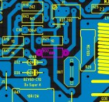
Some problems found.
In one of the boards made (5 models made) you must be carefull about capacitance from the VAS colector to the ground...also be carefull about insulating the VAS colector to the heatsink as in two pcboards the heatsink can be connected to the ground through a screw.
The last Juan pcboards presented a problem related a capacitor in parallel with 47 ohms resistor.... this resistor is in the main VAS transistor (BD139) and it is connected to ground.... the capacitor in parallel should be removed.
The last Zimmer pcboards (white Brazilian ones) had a problem....the CCS that feeds the differential pair uses a BC556 and it is operating too much hot due to the current selected.... it is nearby the differential and the heat is being conducted through the copper tracks and heating, as a result, the differential pair that changes operational point and this results in floating and increasing in the off set voltage....the solution is to reduce the heat, so, the 68 ohms resistor that feeds and sets the current, in the VAS main series transistor emitter, should be increase to 220 ohms into this pcboard.
In other boards, if you feel the BC556 hot, or if you perceive drift in the off set adjusted while cold..then increase the resistor value from 68 to 220 ohms too....150 also works...also 120 works..depends on the board used and the distance, from the VAS (hot) to the differential pair...heat travells in the copper tracks and goes to the differential..the longest the best in this case to use copper tracks as heatsinks to cool down the BC556.
The replacement of this transistor with a BD140 with long leads also fixed the trouble..but become ugly and demand people to increase the lead hole diameter into the pcboard because the BD140 leads are thicker.
We have reached 275 units sold (stereo) and 6 guys reported troubles with heat in the output due to small heatsinks....i suggested them to increase heatsink or reduce power using only 8 and 4 ohms .... also a cooling fan was suggested to them.
One guy reported current drifting...then we reduce the differential VAS current ..we couple two differential together with a heatshrink tube and we detach the drivers from the main heatsink (hot one) and have used small individual heatsinks for them.
Some guys asked more bass to use as subwoofer..the amplifier is linear from 15 hertz up...but for them i suggested to increase the input condenser to 10uf/16 volts, positive to the base and the gain network capacitor increased to 220uf..this does not really increases bass.... just make them out of focus (alike) and reduces high end a little...but the psychological suggestion worked and they guy answered the bass was great...well.... mind has their own issues...we humans ... we are terrible to fool ourselves and to self convince ourselves depending our beliefs..
People are gratefull by the last DIY amplifier...some guys do not like heat like me..hey have reduce current to 100 mA each rail to use small heatsinks and to use a single pair in the output and only 8 ohms...other guys increased to 500 mA (one guy did that to keep coffee hot using heatsink as cup support).
About the Brazilian pcboard there are videos (in portuguese) about it in my youtube channel...my channel is not a paid channel..i am not a partner..there's no advertisement on my channel..i do want to keep my freedom...if they pay you have to respect copyrigth about songs..and they are so crazy that blocked my own song (my own song..composed by me and registered in my name and i am paid because of that)...so.... not a paid channel there:
http://www.youtube.com/user/destroyersoueu
In Facebook you have Dx amp too.
Also you have my own forum:
www.dxamp.com.br
regards and be happy,
Carlos
Last edited:
- Home
- Amplifiers
- Solid State
- Dx Blame ST together Dx Super A