Hello guys!
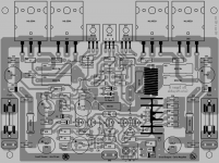
Well! it was not easy at all it took me a long time but I have to keep checking the layout will be ordered soon but I still got more days to check if there is no errors, by the way mister Carlos he did help me and gave me lot lot of guidance, with out him I will not be able to keep going by myself even when he hate to tell people to move stuff on the layouts he have the patience to guide me, I also learn a lot in this last few months it is great!, ok here is the illustration of how it looks now November 15, 2012, but I need more time to make sure is all correct before I order them, also I be happy to share the black and white PDF images and photo sensitive PDF too, ok guys I hope you like this layout that is "Coqui" unique. If all is 100% sure is correct I will post the files need it for etching here hot iron technique and photo sensitive invert too, by the way this is the first layout made here in Puerto Rico if there is a Boricua here he make like it lol, ok guys bye.
Regards
Juan
Attachments
Last edited:
It is looking great.... the best layout ever made to a Dx amplifiers
Well, at least this one matched my needs, not only technicall needs but also aesthetic needs.
This means progress....in other layouts i have tolerated a lot of things i had not total agreement, not to be ofensive or to bother my dear cooperators, the layout designers... As Juan wanted to learn, he was ready to accept my guidance.... this resulted this layout has a lot of mine contribution, this make me happy as i could do it together Juan.... he really made a great job, and i could put my finger on it too.
regards,
Carlos
Last edited:
I have checked tree times.... and you did that 4 times
and even this way we found mistakes.
I suggest you to check once or twice more.
I will do the same.
regards,
Carlos
........................................
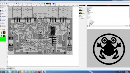
You can see our frog is out of the center, right hand touching the circle....the poor devil has a flat bum, also he eated something not symetrical, stomach left side is bigger than the rigth side..eyes have problem of convergence and the frog must cut it's nails.")
and even this way we found mistakes.
I suggest you to check once or twice more.
I will do the same.
regards,
Carlos
........................................
You can see our frog is out of the center, right hand touching the circle....the poor devil has a flat bum, also he eated something not symetrical, stomach left side is bigger than the rigth side..eyes have problem of convergence and the frog must cut it's nails.
Attachments

Last edited:
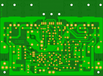
Here are the files for etching method and also the size of the board and many other images for reference and also I will provide information about pitch distance of the components as soon as possible.
Regards
Juan
Regards
Juan
Attachments
I said i am very happy with Juan performance
Satisfied i am with Juan work.... i love each jumper he installed, all them made with my supervision and approved by the Corporation.
We have other foruns, i have some brazilian foruns, in one of them a friend asked me to allow him to develop an output using Fets, as another option and another pcboard that Zimmer will make.
In the reality i gave to the man the scratch of the amplifier, already simulated and with very low harmonic distortion and excelent harmonic distribution to be tweaked, tuned for even better performance while listening.... the guy, the Brazilian, called Naldo, will do that.
Zimmer, the german (South of Brazil) is producing pcboard layout too, more dedicated to feed his own friends in his own town.
Zimmer will make modifications in his pcboard, producing another one, to give folks the option to use Fets in the output.
The main official pcboard layout designer to the Dx Corporation, to international foruns and to the Dx Super A, is Mr. Juan Vargas, from Porto Rico.
Juan can provide boards, if he want, to anybody and anywhere.
Also my brazilian friends can provide boards to anybody and anywhere, but they have made to sell them in Brasil, or to sell them wide world, only if Juan decide not to provide pcboards to the comunity.... then they will have my ok to move on.
regards,
Carlos
Last edited:
I have tested today, it is all right, the Super A and the supply together
Today i have adjusted the stand by current (class A current) to 0.7A each rail.... sound is perfect.
Well, this thing is hot, reason why i am using fan....videos are in portuguese, because of that i am avoiding to post links of portuguese videos here.
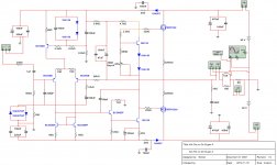
Here you have the schematic, tested, approved and working great.
My transformers are having a voltage drop when i drain 150 watts per rail, then my DC out is 36 volts to each rail (under load conditions)...because of that i have adjusted the supply output to 30 volts in order to let 5 or 6 volts to allow the regulator to operate...then i had, during test, 6A to each rail (180W) and the voltage drop was 0.1 to 0.2 volt...so, calculate and you will see it really stabilizes the voltage, in special to Class A as current does not variate to much fast...the 3300uf condenser make this circuit slow, to use together AB amplifier it is better to reduce it to 220uf.
To operate this supply you have to connect DC rectified (by diodes) to the input that is in the left side..then you adjust the trimpot to the voltage you want.... transformer is 30 plus 30 AC volts... you do not need filters... the input 10.000uf per rail will be enougth to 150 watts per rail, and no AC mains frequency noise appear in the output (very small noise, almost nothing)
Use heatsinks to your output transistors...i am using three in parallel to each rail...also i am using power equalizing resistors in series with these transistor emitters (0.22 ohms or 0.33 ohms)
To know the power you will have drained from this regulator, them make the series pass power transistor colector voltage - (minus) emitter voltage and them multiply by the current...then you will have the power developed into the series power transistors..use an aluminium blade measuring 10 by 10 centimeters (squared and 1.0 to 1.5 milimeters thick) to each 10 watts of dissipation.... or equivalent.
In my case i am draining only 2 amperes each rail...input voltage is more or less 38 Volts under this condition, and i have adjusted to 30 volts my output voltage.... so, i have 8 volts multiplied by two that results in 16 watts each rail of heat.... i need 4 blades of aluminium to solve my problem.
regards,
Carlos
Today i have adjusted the stand by current (class A current) to 0.7A each rail.... sound is perfect.
Well, this thing is hot, reason why i am using fan....videos are in portuguese, because of that i am avoiding to post links of portuguese videos here.
Here you have the schematic, tested, approved and working great.
My transformers are having a voltage drop when i drain 150 watts per rail, then my DC out is 36 volts to each rail (under load conditions)...because of that i have adjusted the supply output to 30 volts in order to let 5 or 6 volts to allow the regulator to operate...then i had, during test, 6A to each rail (180W) and the voltage drop was 0.1 to 0.2 volt...so, calculate and you will see it really stabilizes the voltage, in special to Class A as current does not variate to much fast...the 3300uf condenser make this circuit slow, to use together AB amplifier it is better to reduce it to 220uf.
To operate this supply you have to connect DC rectified (by diodes) to the input that is in the left side..then you adjust the trimpot to the voltage you want.... transformer is 30 plus 30 AC volts... you do not need filters... the input 10.000uf per rail will be enougth to 150 watts per rail, and no AC mains frequency noise appear in the output (very small noise, almost nothing)
Use heatsinks to your output transistors...i am using three in parallel to each rail...also i am using power equalizing resistors in series with these transistor emitters (0.22 ohms or 0.33 ohms)
To know the power you will have drained from this regulator, them make the series pass power transistor colector voltage - (minus) emitter voltage and them multiply by the current...then you will have the power developed into the series power transistors..use an aluminium blade measuring 10 by 10 centimeters (squared and 1.0 to 1.5 milimeters thick) to each 10 watts of dissipation.... or equivalent.
In my case i am draining only 2 amperes each rail...input voltage is more or less 38 Volts under this condition, and i have adjusted to 30 volts my output voltage.... so, i have 8 volts multiplied by two that results in 16 watts each rail of heat.... i need 4 blades of aluminium to solve my problem.
regards,
Carlos
Attachments
Last edited:
Since i got recently a JVC amp of average construction for free i m tempted
to get the Super A VC5022 part for my mosfet amplifier but before proceding ,
i would be curious if your discrete implementation (used in the AX5) works
accurately.
In principle the idling current is about 50mA , the Super A circuit role
is just to keep both output devices conducting whatever the output power ,
hence it is a non switching circuit.
My circuit is not used in this model.... well, at least i have made by myself
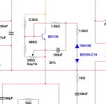
It is just a zener sending positive voltage to the VBE multiplier base when we reach a couple of watts in order to reduce the DC stand by current (bias) to the normal level i use into the Dx Blame ST....in other words, it is a Class AB amplifier and i have adjusted the current to the output transistors to 250 mA to each rail, or 500mA to each rail....today i have tested using 700mA to each rail.... when i crack the volume up, the ouput line voltage crosses the zener diode, and then two attenuating resistors and this feed more current to the VBE multiplier transistor base that readjust its operational point reducing the current to 20ma per rail.
Just that... a very simple circuit, a zener, one 1N4148 diode, one capacitor and two resistors...this feeds the VBE multiplier transistor base with positive voltage.... this reduces the ddp from colector to emitter reduing the bias to the output transistors....the VBE multiplier is standard.
JVC uses a much more sophisticated and complicated circuit, i do think mine do the job...just that.
regards,
Carlos
Here you see.... you adjust the bias trimpot to
700mA each rail, then we increase the volume..when the zener diodes senses 6 watts RMS it starts to conduct and goes reducing the current...at 70 watts the DC current is 33mA per rail.
Very simple, and because of that it is very good.
regards,
Carlos
700mA each rail, then we increase the volume..when the zener diodes senses 6 watts RMS it starts to conduct and goes reducing the current...at 70 watts the DC current is 33mA per rail.
Very simple, and because of that it is very good.
regards,
Carlos
Attachments
- Home
- Amplifiers
- Solid State
- Dx Blame ST together Dx Super A