This one is very nice, did it exists in 10K ?
All std values normally, for 1 EUR only.
http://www.epcos.com/inf/50/db/ntc_09/ProbeAss__B57045__K45.pdf
I saw that; but the only source, for us, is mouser 'non stocked'.
Finding parts is a nightmare !
As usual
Adn what about it:
NTCALUG02A103G Vishay/BC Components | Mouser
Sajti
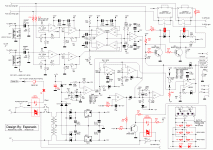
Thanks, thanks thanks.version 3... check for values pls.
I check this night., At first sight, just the inputs to preamp relay are at ground. Thanks too for having noticed the design error, there.
Btw, what software do-you use ?
Last edited:
It is a big job to research comps, build CAD lib's symbols for sch & foot prints for layout, doing the layout part is actually the fun part after all the dog work is done. I do not trust the free libs from the CAD vendors, as they are riddled full of errors. If it ain't done right then you can waste monies quite easily on a pcb that has faults and requires barnacles.
Mr. Esperado, have you every done a pcb layout before? I can help you with with advise, since I know this task quite well.
Rick
Mr. Esperado, have you every done a pcb layout before? I can help you with with advise, since I know this task quite well.
Rick
Exactly correct. The part building from real data is critical, one of the reasons, besides not wishing to be the pacing item for everything, that I have always farmed out layout, albeit well-supervised.It is a big job to research comps, build CAD lib's symbols for sch & foot prints for layout, doing the layout part is actually the fun part after all the dog work is done. I do not trust the free libs from the CAD vendors, as they are riddled full of errors. If it ain't done right then you can waste monies quite easily on a pcb that has faults and requires barnacles.
Mr. Esperado, have you every done a pcb layout before? I can help you with with advise, since I know this task quite well.
Rick
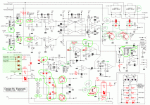
Here they are.version 3... check for values pls.
The two diodes Z1, Z2, protecting the power mosfets can be replaced by a Varistor,(depending of the voltage of MOSFETS used, what do you think?
Some color changes, to allow more choices, like impedance values for input preamp, transistor, to can use any ones diyers can have.
Some errors in resistances values, corrected, one path too.
If changes of colors bores-you, i can do-it myself on your image.
Changes are outlined in green.
Attachments
It was one of my favorite jobs in the research and development office i was working in, so many decades ago. We did that by hand, no computers at this time. I loved that too.Mr. Esperado, have you every done a pcb layout before? I can help you with with advise, since I know this task quite well.
Rick
Parts were more simpler to find, as our suppliers did the job to propose parts according our requisites ( and not so many choice).
After that, i had people doing-it both the schematics designs and the PCb, and after, an other professional life, away from Industry, as a sound ingeneer.
Where we are, now, is all the active parts had been chosen and if you can help, you are welcome like God.
I believe king Alex mm is having a look at this thread, and, may-be will design one of his nice PBs. for this project.
All the datas will be centralized here:
http://www.esperado.fr/images/stories/protection/
For coolet, one of the the Varistor to can replace Z1& Z2 can be:
VDRS05A030BSE
Last edited:
In 70s, creating PCBs was a very manual process. First, design the layout, with pencils and papers (a lot of  .
.
Then opaque tapes of different width for the tracks, and transfers for pellets, on graph tracing paper.
Then, isolation by contact on special high contrast films (Kodalith) . Development and filling of potential holes.
It was not very different of what you could do at home, at this time.
Then opaque tapes of different width for the tracks, and transfers for pellets, on graph tracing paper.
Then, isolation by contact on special high contrast films (Kodalith) . Development and filling of potential holes.
It was not very different of what you could do at home, at this time.
We had a draughtsman do pcb layouts for us using tape and clear film.
I didn't know much about pcb layout in those days and we used to have awful hum in pcb's. It wasn't until years later I learned about ground loops.
I bought an early version of EasyPC and that gave me a start with laying out pcb's.
However it kept crashing and had loads of bugs in it so I decided to write my own pcb software. At least then if I found a bug I could fix it myself.
yes guys, i go back as far as tape & mylar as well.= limited capabilities
If i was not busy working on other projects i'd work on this one. I have copy of orcad.
it is very helpful to have a bom of mfg & mfg part #'s to see what libs I have already & what needs to be built.
If i was not busy working on other projects i'd work on this one. I have copy of orcad.
it is very helpful to have a bom of mfg & mfg part #'s to see what libs I have already & what needs to be built.
What platform does this SW run on? capabilities?so I decided to write my own pcb software.
What platform does this SW run on? capabilities?
Windows PC.
Touch screen compatible (single touch) + slide pan (Windows 7 amd multi touch only)
2013 Windows version of PCBCAD50 PCB DESIGN SOFTWARE with 127 LAYER AUTOROUTER.
Runs on Windows XP, Windows Vista and Windows 7 and Windows 8.
Fully supported product sent by first class recorded post.
Schematic and PCB symbol designer wizards.
Auto creates SIL, DIL, circular and QUAD PCB footprints from your parameters.
Schematic entry with auto convert schematic to PCB ratsnest, unconnected pin scanner and single ended net scanner.
PCB entry with 127 layer rip up and retry auto-router with clearance and continuity check.
Integrity checker, compares schematic and PCB for differences.
Component locater.
Parts list output.
Schematic/PCB component auto-renumbering and re-annotation.
RS274X Gerber file generator and NC/Excellon drill file generator.
Pick and place file generator with fiducial option.
XNA based 3D PCB viewer module.
Output schematic to printer auto-sized.
Output PCB to printer in 4:1, 2:1 and 1:1 scaling and mirroring about x and y axis.
Merge schematics and merge PCB's.
Library scanners for fast component selection.
Gerber file viewer (PCBCAD50 files only)
Component locater, block-mode for repeats, shifts, rotations etc.
Net optimizer for shortest routes.
Auto component placers for minimum routing.
Recursive auto-autoplace, rotational autoplace and swap autoplacer.
Auto-place and route recursively function for lazy PCB design.
Unconnected pin scanner.
Forward annotation function from schematic to PCB.
Screen capture to bitmap file in schematic and PCB entry.
PCB's up to 50 by 50 inches.
127 copper layers.
127 resist layers.
127 power-plane layers, each layer can be connected to a different NET.
2 silk layers (upper/lower)
Comes with symbol libraries, 4000, 7400, smd4000, smd7400 and general as standard.
User manual in each module
PCBCAD50?
Nigel,
Nice CAD package and you wrote this SW yourself? = cool
Do you have a web site?
Would GerbTool be able to read the CAM output data from PCBCAD50?
And the cost of such a SW product?
Nigel,
Nice CAD package and you wrote this SW yourself? = cool
Do you have a web site?
Do not understand why? if you are outputting RS274xGerber file viewer (PCBCAD50 files only)
Would GerbTool be able to read the CAM output data from PCBCAD50?
And the cost of such a SW product?
For coolet, one of the the Varistor to can replace Z1& Z2 can be:
VDRS05A030BSE
i suggest include it in the building documentation as alternatives
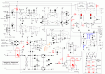
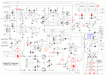
version 3.01 >>> proofread pls and alternative for remote (if you like)
Attachments
- Status
- This old topic is closed. If you want to reopen this topic, contact a moderator using the "Report Post" button.
- Home
- Amplifiers
- Solid State
- An ultimate amp protection circuit ?


