Hi Guys,
My system is (was) a 1986 sony XO550W stereo cassette tuner. Its main IC has failed (an STK4152ii) and it needs to be replaced (as confirmed by a repair shop).
My attempt is to try and investigate how this happened. I will describe the events that led to the failure of the unit one by one.
1) I was in the process of doing some routine clean up in the unit with the covers off (It was minor clean up - I didnt take any boards/connectors out or adjust anything - just the covers off and wipe off dust/cob webs).
2) After the clean up was done, before putting the cover back on, I decided to turn it back on to see if everything was working ok.
3) When power was turned on, everything looked ok but with one problem - the tuner was not getting any power (I assumed this because the tuner light on the tuning dial was not on - but the tape deck was working ok).
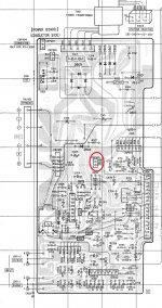
4) Thinking that this was a problem with power supply to the tuner, I slightly pushed and jiggled the tuner power plug (CNP905 - circled red on attached schematics) WITH the power still on. (as stupid as it may sound )
)
5) To my horror, the unit died instantly (all power went off) with only a solitary click of the relay (RY901) heard seconds later.
6) From that point the unit will not power on and only the relay will click a few seconds later (when the unit was working there was no delay in the relay click - it happened simultaneouly with the power switch)
7) Then later I was told by an exparienced repair shop that the main audio IC has failed and it need to be replaced.
So, sorry for the long post, but this is where I'm at now confused as to what I caused for this unit to fail. It was obviously a short between some power lines or IC pins, but which pins would cause this type of failure in an STK IC? Or was it something else that could have caused it.
I can provide more clearer schematics if required.
Hopefully this provides a good dicussion.
Thanks.
My system is (was) a 1986 sony XO550W stereo cassette tuner. Its main IC has failed (an STK4152ii) and it needs to be replaced (as confirmed by a repair shop).
My attempt is to try and investigate how this happened. I will describe the events that led to the failure of the unit one by one.
1) I was in the process of doing some routine clean up in the unit with the covers off (It was minor clean up - I didnt take any boards/connectors out or adjust anything - just the covers off and wipe off dust/cob webs).
2) After the clean up was done, before putting the cover back on, I decided to turn it back on to see if everything was working ok.
3) When power was turned on, everything looked ok but with one problem - the tuner was not getting any power (I assumed this because the tuner light on the tuning dial was not on - but the tape deck was working ok).
4) Thinking that this was a problem with power supply to the tuner, I slightly pushed and jiggled the tuner power plug (CNP905 - circled red on attached schematics) WITH the power still on. (as stupid as it may sound
)5) To my horror, the unit died instantly (all power went off) with only a solitary click of the relay (RY901) heard seconds later.
6) From that point the unit will not power on and only the relay will click a few seconds later (when the unit was working there was no delay in the relay click - it happened simultaneouly with the power switch)
7) Then later I was told by an exparienced repair shop that the main audio IC has failed and it need to be replaced.
So, sorry for the long post, but this is where I'm at now confused as to what I caused for this unit to fail. It was obviously a short between some power lines or IC pins, but which pins would cause this type of failure in an STK IC? Or was it something else that could have caused it.
I can provide more clearer schematics if required.
Hopefully this provides a good dicussion.
Thanks.
Attachments
Yea i thought that too at first, but i think the fact the relay goes into protect mode would indicate problems in the amplifier section, right?
I mean if it was just Q905 or R923 burnt, i dont think it would cause the whole system to shut down, wouldn't it?
I think if we start from the fact that the relay is in protect mode and work backwards from there, it would lead us to why it failed.
if we could get some insight on what type of scenerio would cause the protection circuit on the schematic to be activated, itd be great.
Thanks Guys
Hi,
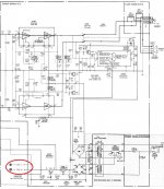
Did you check the fuse to see if it is good? There it is a wire coming out between the transistor and the fuse that the schematic do not show it. The relay it is enable for overload, offset and AC off det. It is possible that one of this signal need that voltage missing. The best thing to do it is find out if the voltage it is OKAY coming out of the transistor. Then we can find out why the relay it is enable.
Did you check the fuse to see if it is good? There it is a wire coming out between the transistor and the fuse that the schematic do not show it. The relay it is enable for overload, offset and AC off det. It is possible that one of this signal need that voltage missing. The best thing to do it is find out if the voltage it is OKAY coming out of the transistor. Then we can find out why the relay it is enable.
Both fuses are ok, but I will confirm the voltage from the Q905/R923.
If Q905 is at fault, does it explain this behaiviour? Assuming Q905 has failed, what would happen to the relay? Would it start and go in to protect a few milliseconds later.. ???
For me, even though Q 905 fails, D904 will still supply a ON signal to the protect IC (IC903) and the relay will still turn on. It doesn''t do that in this situation, and the relay turns off few milliseconds later
Hi,
If you want check IC903 pin 1 "overload" should read 0 volt. Zero means it is OKAY.
IC903 pin2 "offset" should read 0 volt. Zero means it is OKAY. If pin 2 read zero then you do not have any problem with the speaker outputs offset. Let us know if you have output voltage from the
If you want check IC903 pin 1 "overload" should read 0 volt. Zero means it is OKAY.
IC903 pin2 "offset" should read 0 volt. Zero means it is OKAY. If pin 2 read zero then you do not have any problem with the speaker outputs offset. Let us know if you have output voltage from the
stk might fail without a reason
Inside the STK there is a lot of things in a very small area. Often tracing the fault down to electric reasons is not 100% correct .
One of a common failure inside an STK but also very common between normal transistors is a mechanical failure .
Transistors are glued on the plate of the STK or the die is arc welded on the plate of a TO3P transistor Often heat is the worst enemy and will eventually result to failure .
Warming up the IC or TR from room temperature to operation temperature every day could stress the method of attaching ...also good to remember is that STK by nature are not completely airtight ...To your surprise i can inform you that some of first generation 2N2905 style transistors wasn't also air tight ..Now air can carry moisture that is also an enemy in such a case .
One of them gets a bit loose and then kabooom without other obvious reasons .
it is not uncommon between repair people that there is a chance that a transistor measure properly with a DVM measures also proper hfe but fails when connected to operating voltage ....
Kind regards
sakis
Last edited:
Yes there is no 10V at Q 905 emitter and no 14V at Q905 Collector. Its open circuit. it seems either Q905 or R923 or both are failed. Seems repair shop was wrong about the STK
This means that IC903 gets AC off det OK signal and the relay turns on a few milli seconds later (I made a mistake before, the relay turns does ON after delay) But i still dont know why the relay takes a while to turn on - it didn't do this before breaking- the relay turned on instantly with power switch -. not sure on this...
This means that IC903 gets AC off det OK signal and the relay turns on a few milli seconds later (I made a mistake before, the relay turns does ON after delay) But i still dont know why the relay takes a while to turn on - it didn't do this before breaking- the relay turned on instantly with power switch -. not sure on this...
Last edited:
- Status
- This old topic is closed. If you want to reopen this topic, contact a moderator using the "Report Post" button.
- Home
- Amplifiers
- Solid State
- Sony system failure - full investigation thread