Hi there,
I am newbie with mosfet and I am trying to understand a power amp schematic with these Hitachi complementary transistors. I would appreciate if someone could tell me what's the purpose in using bjts from source to gate in the schematic below and how is this topology called (if there is any) to search more information and study it with more detail.
Thanks in advance.
Attachments
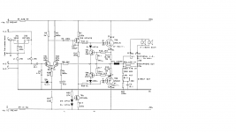
The bjts are used for current limiting (protection). Looking at one side, when the voltage across R13 reaches sufficient to turn on TR4, then TR4 begins to "short" the drive to the FET and provides limiting. R11 and R12 make a divider. When the voltage on the base of TR4 reaches 0.7 volts the limiting begins.
The amp is a standard configuration. DC coupled with a LTP (long tailed pair) input stage and source follower outputs. The voltage gain of the circuit is R8 divided by R6. C3 ensures the gain rolls off at low frequencies and is unity (1) at DC.
C3 and C1 could usefully be made a little larger.
The amp is a standard configuration. DC coupled with a LTP (long tailed pair) input stage and source follower outputs. The voltage gain of the circuit is R8 divided by R6. C3 ensures the gain rolls off at low frequencies and is unity (1) at DC.
C3 and C1 could usefully be made a little larger.
you may want to limit the low frequencies of a guitar amp vs say a bass amp or home audio amp where you want the full extension.
Low "E" on a guitar is 82hz so limiting the lows down around 30-40hz would clean up the low end a bit and most guitar speakers don't have a lot of excursion capability so limiting the amp down around 30-40hz would help protect the speakers against mechanical damage!
Low "E" on a guitar is 82hz so limiting the lows down around 30-40hz would clean up the low end a bit and most guitar speakers don't have a lot of excursion capability so limiting the amp down around 30-40hz would help protect the speakers against mechanical damage!
- Status
- This old topic is closed. If you want to reopen this topic, contact a moderator using the "Report Post" button.