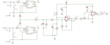
Here is the circuit with the suggested input filter installed. I don't know if my math is right and and unfortunately I don't have access to an oscilloscope to test it out. Is this what you were recommending? The capacitive reactance should be just under 16 Ohms and the cutoff frequency should be 3.3kHz.
This is limiting offset current if I understand it correctly. Would this be something to consider for op amps with FET inputs as well?
Feel free to critique this circuit. I know its simplistic as far as audio systems go but it may be fairly unique in its application. The unit and radios are back mounted with the volume controls and transmitter selector mounted on the front of the vest. The system works very well in the prototype which is a bulky double sided mixed smd/through hole setup. It remains to be seen how well it works in a densely packed, double sided, fully smd board.
- Status
- This old topic is closed. If you want to reopen this topic, contact a moderator using the "Report Post" button.