we all know that its better if possible instead of using 2x10.000 mfd in amplifier to use 4X 4700.
known so far + is that esr drops and - that distribution of ground and power traces on the pcb might cause complication
Original question is like that .
Suppose that from the nature of the application it is impossible to use even 4700 capacitors .... the closest solution can be something like 20-30 capacitors of 220mfd at the rated voltage per rail
Anyone thinks its possible and then any comments on the plus or minus of the case ?
Kind regards
sakis
hello
it is assumed that the application is for low frequency charging/discharging i.e. charging thru 50/60Hz and discharging thru audio frequencies content current sinks. IN THAT CASE, the inductance presented by a properly distributed wire grid or appropriately thick and wide copper plane is not an issue. it is assumed that higher frequency content is taken care of locally at the supply pins of ICs or transistors with small 100nF caps. it is more likely that any distributed resistance will be more crucial.
it is assumed that the application is for low frequency charging/discharging i.e. charging thru 50/60Hz and discharging thru audio frequencies content current sinks. IN THAT CASE, the inductance presented by a properly distributed wire grid or appropriately thick and wide copper plane is not an issue. it is assumed that higher frequency content is taken care of locally at the supply pins of ICs or transistors with small 100nF caps. it is more likely that any distributed resistance will be more crucial.
I am always using some kind of capacitance multipliers when it comes to high currents, or regulated PSUs for small ones. Ears can't be trusted, but IMHO it sounds better than a huge capacitor bank. For local bypassing I've found out that usual 100nF on legs may do harm as well, so I always use something like 47uF+100nf, soldered directly to transistor/IC legs, not on PCB. I am not sure about what are you trying to achieve, but I would give a try to paralleled tons of small capacitors, but then you should take care of PCB layout. I would probably solder them with thick wire.
Last edited:
hand full of info ..all seems useful.
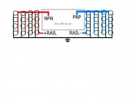
available space is the issue there and of course the application is Class AB audio amplifier .
down under i will post a generic schematic of the lay out and we can proceed our talk based on that .
thanks for the help so far
kind regards
sakis
available space is the issue there and of course the application is Class AB audio amplifier .
down under i will post a generic schematic of the lay out and we can proceed our talk based on that .
thanks for the help so far
kind regards
sakis
Attachments
10k uf caps are pricey and the cheaper ones are too tall to fit in my PV 1.3k amp. I've installed 4x 4700 uf on one channel, and inventory 6x 3300 uf on the other channel. Since PA amps are subject to being banged around, I glued them in a sandwich of polycarbonate plastic (surplus window plastic) with holes drilled for the snap in leads. I screwed the assemblies to the PWB with 2" #6 screws with a plastic washer under to distribute the weight load. I bussed the leads of the caps together with #18 wire, and drilled an extra hole in the cap PWB so the current goes in 2 places instead of one. This circle of wire offers the possibility of extra hum pickup due to the loop, but I don't hear anything objectionable. oh, about the laminated busbar comment, Peavey used extra thick copper lands on the cap and rectifier PWB- I've never seen it that thick on any other product.
The shorter caps leave room to space the driver boards out more and leave room for KK series crimped connectors for the wire harness, instead of the push-in wire connectors with side entry Peavey used. This is for the harness that connects the driver PWB to the output transistor PWB. I've had lost connections and somebody else on here lost the ground feed of a PV8, so I view this as a reliability improvement.
PV 1.3k has all the PS caps 12" from the output transistors, so I'm not expecting highly accurate high frequency bells or piano reproduction as designed. After I get it working stably, I may experiment with 1 uf of ceramic caps to bypass the rails on the output transistor PWB, but not until I kill the oscillations I'm getting dead. [ I found there is supposed to be a 180 ohm resistor parallel a 0.22 uf cap between the two bass driver lines on the output transistor PWB. A side that doesn't oscillate has a 1.2 k resistor and no cap installed (looks like a factory brand resistor), the B side that RF oscillates has a burned cinder and burnt land there. ]
Last edited:
i guess you are not expecting high peak currents. if however, the caps are expected to supply considerable current and thick wires are not possible i suggest you use a wire grid instead of single 'fingers' or even star wiring. a wire mesh/grid would minimize the resistance for the possible high currents.
That is a rather interesting point since in the same capacitance between different arrangement IE one big cap or 20 small what makes arrangement A versus B to be able to deliver more or faster current ?
So if we take as a fact that pcb is not an issue either bars or thick traces/planes are used to ensure maximum delivery is there other reasons or documentation that support the above ?
something is telling me that the reaction time will be better with many parallel caps instead of one ..But of course this is what i think .....
I may as well construct and see .... i don't think that behavior like that can be simulated or that there is any documentation of something previously recorded in such an issue .
Kind regards
sakis
i think you may have misunderstood me. This is not a question of faster current delivery since we assumed that the frequency content is not based on pulses and the inductance present, even if it is of the order of hundreds of nano Henries is not an issue for signals of a few KHz bandwidth.
Instead, what i meant, is that by using finger wiring of the same thickness thru out or if the thickness is not sufficient at the proper summing branches the resistance might cause a significant drop for high peak currents. a wire grid (square grid if you will) will distribute a lot of parallel small "resistors" which will alleviate any possible problems.
Instead, what i meant, is that by using finger wiring of the same thickness thru out or if the thickness is not sufficient at the proper summing branches the resistance might cause a significant drop for high peak currents. a wire grid (square grid if you will) will distribute a lot of parallel small "resistors" which will alleviate any possible problems.
- Status
- This old topic is closed. If you want to reopen this topic, contact a moderator using the "Report Post" button.
- Home
- Amplifiers
- Solid State
- solid state capacitor question