If you are a beginner at DIY audio electronics I'd humbly suggest you look into proven DIY designs that are a little, no actually quite a bit, more modest than sighting 1kW amplifiers. There's lots of stuff here, some fairly generic others exotic that would be a likely better place to start.
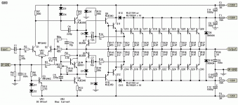
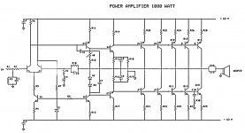
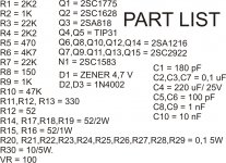
In looking at the schematic and parts list some of the values seem less than ideal to me. Also why is there an output Zobel at the bases of the 2SC2922 outputs and not on the actual speaker output? I don't suggest trying to build this as it is presented.
Even assuming zero losses I'd think not quite 1000W but let's see what we get anyhow. Let's give the best chance for a high output and talk of a 4R load.
63Vpk^2/4R=992.25Wpk that would be ~496W average power in a perfect lossless world. There is no such thing as RMS watts, RMS voltage and current but power is average. This is as close as you are likely to get and the value was still rounded up.
Now the SOA curves indicate just over 3A per device at the supply voltage for the outputs specified on the parts list. 63V/4R=15.75A total peak current divided by 5 pairs is 3.15A, right at the hairy edge of the SOA and flirts with second breakdown. This also does not account for a reactive load. So a nominal 4 ohm load in the real world would likely violate the SOA of the output stage. Also there is no protection at all considering how close it would potentially be to releasing all it's magic smoke.
Let's account for some losses and see where we go from there. Start with the power supply and assume under no / minimal load such as a quiescent state and your mains is delivering its ideal nominal voltage that you actually have 63V rails. Now lets say the mains is down near the allowable -10% (for my area at least) mark, that would reduce the rails down to about 56V. Of course bulk supplies that would likely power a project as this aren't totally stiff either and let's assume a further 6% loss under full load. Now our rails are in the neighbourhood of 52.5V. Now let's look at the OPS. Assume hard clipping, the output transistors themselves have a saturation voltage of 2V, so with our drooping mains and supply rails we can say perhaps realistically a 50V peak output to the load.
Now things look more like 50V pk^2/4R=625W pk, or 312W average.
Now the VAS has an unusually large amount of degeneration with R11 being 330 ohm and a VAS current of 12mA. This will cause the loss of another 4V of swing from the positive rail. Also the CCS being supplied by a 4V7 zener will cause about 4V loss of swing towards the negative rail.
What's left? 46V pk^2/4R=529W pk, or 264W average.
At least with some losses accounted for the OPS devices are not so close the their SOA limit but a highly reactive load would still present a danger to them. The 1000W claim seems a little fluffed up and in reality a 1000W amplifier would be a little more involved than the design presented here.
Find a nice, honest 50W to 100W design for a place to start if your skills are decent or if some of the design work id already done and tested for you, such as a group buy on boards with an established group of successful builders. Otherwise start smaller and work up from there. My and that's exactly what it's worth...
In looking at the schematic and parts list some of the values seem less than ideal to me. Also why is there an output Zobel at the bases of the 2SC2922 outputs and not on the actual speaker output? I don't suggest trying to build this as it is presented.
Even assuming zero losses I'd think not quite 1000W but let's see what we get anyhow. Let's give the best chance for a high output and talk of a 4R load.
63Vpk^2/4R=992.25Wpk that would be ~496W average power in a perfect lossless world. There is no such thing as RMS watts, RMS voltage and current but power is average. This is as close as you are likely to get and the value was still rounded up.
Now the SOA curves indicate just over 3A per device at the supply voltage for the outputs specified on the parts list. 63V/4R=15.75A total peak current divided by 5 pairs is 3.15A, right at the hairy edge of the SOA and flirts with second breakdown. This also does not account for a reactive load. So a nominal 4 ohm load in the real world would likely violate the SOA of the output stage. Also there is no protection at all considering how close it would potentially be to releasing all it's magic smoke.
Let's account for some losses and see where we go from there. Start with the power supply and assume under no / minimal load such as a quiescent state and your mains is delivering its ideal nominal voltage that you actually have 63V rails. Now lets say the mains is down near the allowable -10% (for my area at least) mark, that would reduce the rails down to about 56V. Of course bulk supplies that would likely power a project as this aren't totally stiff either and let's assume a further 6% loss under full load. Now our rails are in the neighbourhood of 52.5V. Now let's look at the OPS. Assume hard clipping, the output transistors themselves have a saturation voltage of 2V, so with our drooping mains and supply rails we can say perhaps realistically a 50V peak output to the load.
Now things look more like 50V pk^2/4R=625W pk, or 312W average.
Now the VAS has an unusually large amount of degeneration with R11 being 330 ohm and a VAS current of 12mA. This will cause the loss of another 4V of swing from the positive rail. Also the CCS being supplied by a 4V7 zener will cause about 4V loss of swing towards the negative rail.
What's left? 46V pk^2/4R=529W pk, or 264W average.
At least with some losses accounted for the OPS devices are not so close the their SOA limit but a highly reactive load would still present a danger to them. The 1000W claim seems a little fluffed up and in reality a 1000W amplifier would be a little more involved than the design presented here.
Find a nice, honest 50W to 100W design for a place to start if your skills are decent or if some of the design work id already done and tested for you, such as a group buy on boards with an established group of successful builders. Otherwise start smaller and work up from there. My
 and that's exactly what it's worth...
Hi,
There is no such thing a a simple 1KW amplifier and the above circuit is very poor, wrong in places and simply very niave, and nowhere near a real 1KW.
Project 117
rgds, sreten.
There is no such thing a a simple 1KW amplifier and the above circuit is very poor, wrong in places and simply very niave, and nowhere near a real 1KW.
Project 117
rgds, sreten.
R5 just absorbs some of the voltage from the LTP current source. R9 prevents the VAS current source from latching up when the amp clips. It WILL do this if you just tie the bases of the current sources together. Try it sometime (with a low power amp). It's really annoying, and the sims won't necessarily show a problem.
+/-63 for a kilowatt. Right. I guess they assume everyone's using 8kVA toriods to get regulation and 1 ohm loads to get power. I really wish they'd stop this. There is probably enough SOA for a real world power supply and load, but it's a 150W amplifier. 200W at the outside, assuming you spent $300 on the toroid. And there are way better 150W amplifier deisgns out there.
Want a kW? Try one of the Workhorse or Apex designs - or clone a big QSC. Even "Project 117" is just a starting point not a complete amplifier.
thnks for all input and sugestion...,and yes i just prepare for project 117R5 just absorbs some of the voltage from the LTP current source. R9 prevents the VAS current source from latching up when the amp clips. It WILL do this if you just tie the bases of the current sources together. Try it sometime (with a low power amp). It's really annoying, and the sims won't necessarily show a problem.
+/-63 for a kilowatt. Right. I guess they assume everyone's using 8kVA toriods to get regulation and 1 ohm loads to get power. I really wish they'd stop this. There is probably enough SOA for a real world power supply and load, but it's a 150W amplifier. 200W at the outside, assuming you spent $300 on the toroid. And there are way better 150W amplifier deisgns out there.
Want a kW? Try one of the Workhorse or Apex designs - or clone a big QSC. Even "Project 117" is just a starting point not a complete amplifier.

now i just finish build H900 by Apex...,clean sound and high power...i love it.
but i'm still looking for a Kw ab amp 4-2 R,
regards.
- Status
- Not open for further replies.
- Home
- Amplifiers
- Solid State
- SIMPLE 1KW AB Amplifier

