My little Tringlophone!
Hello everyone!
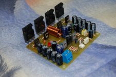
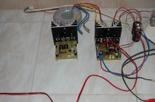
I have completed a module Tringlophone my tests but I will tomorrow. For my test channel will be equipped with a Circlophone and the other channel with Tringlophone.
There is just one little problem, I don 't have to 470UF capacitor C2 and C7 then I have temporarily put the 220uf (I hope that it's going).
While waiting for my return to the sound (hopefully), here are some pictures.
Regards!
Hello everyone!
I have completed a module Tringlophone my tests but I will tomorrow. For my test channel will be equipped with a Circlophone and the other channel with Tringlophone.
There is just one little problem, I don 't have to 470UF capacitor C2 and C7 then I have temporarily put the 220uf (I hope that it's going).
While waiting for my return to the sound (hopefully), here are some pictures.
Regards!
Attachments
Very niceHello everyone!
I have completed a module Tringlophone my tests but I will tomorrow. For my test channel will be equipped with a Circlophone and the other channel with Tringlophone.
No problem for the initial tests.There is just one little problem, I don 't have to 470UF capacitor C2 and C7 then I have temporarily put the 220uf (I hope that it's going).
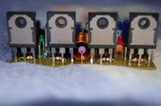
Be sure to fit a sufficient heatsink: this is pure class A, and it comes with the heat...
Very nice sound quality!
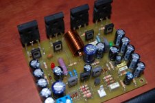
After a nice smoke and change some components finally the music out!
To explain a little I had old BD140 were black that as BD139 of now and I do not necessarily put the right transistors (resistor, LED and 1N4148 grilled ).
I must say I am very surprised by the sound quality of this amplifier yet supplied with 27V (supply of very poor quality). For my testing shows that the heatsink is too small for heating here!
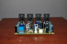
I have yet to compare with Circlophone but I'll do it as soon as possible because I have a better power supply makes for good returns.
Elvee, bravo for the sound of this amp is excellent, very dynamic and seems much more powerful it is.
At higher volumes the green LED varies in intensity, I think my power is concerned.
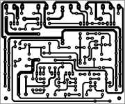
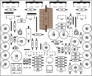
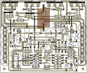
I prepare my files for PCB making this amplifier if some are interested.
Regards!
After a nice smoke and change some components finally the music out!
To explain a little I had old BD140 were black that as BD139 of now and I do not necessarily put the right transistors (resistor, LED and 1N4148 grilled ).
I must say I am very surprised by the sound quality of this amplifier yet supplied with 27V (supply of very poor quality). For my testing shows that the heatsink is too small for heating here!
I have yet to compare with Circlophone but I'll do it as soon as possible because I have a better power supply makes for good returns.
Elvee, bravo for the sound of this amp is excellent, very dynamic and seems much more powerful it is.
At higher volumes the green LED varies in intensity, I think my power is concerned.
I prepare my files for PCB making this amplifier if some are interested.
Regards!
Attachments
Great!After a nice smoke and change some components finally the music out!
That kind of things happens but you've been relatively lucky: the damages could have been more seriousTo explain a little I had old BD140 were black that as BD139 of now and I do not necessarily put the right transistors (resistor, LED and 1N4148 grilled ).
Normally, at the maximum power the current variation through both LEDs is only a few percents. If there is a visible flicker, this probably means you're saturating or clipping somewhereAt higher volumes the green LED varies in intensity, I think my power is concerned.
Thanks for your service to the community.I prepare my files for PCB making this amplifier if some are interested.
Due to the polarity of the output transistors and the combination of a number of other factors, this arrangement is more advantageous as it results in an inherent power supply rejection.Why positive ground???
In theory yes, but the loss of swing due to the Vgs would reach a crippling pointAt post 76, I see darlingtons. . . so might fets be workable?
Let us look at how the circuit works.
Basically, it comprises two stages: a voltage amplifier having a gain a little greater than 20dB, and a unity gain power buffer.
Let us deal quickly with the VAS: it is the uninteressant part of the circuit (I somewhat had a lack of inspiration at the time).
It is simply a common emitter amplifier based on a CFP (Q12, Q13) for improved linearity.
It is followed by an interstage buffer (Q10, Q11) required to drive the output stage in good conditions.
Nothing particularly smart or original there, the VAS does its job properly, no less, no more.
The output stage:
Now, the interesting bit.
It is a Tringlotron topology, although it isn't apparent at first sight: it looks more like a Quaplotron (quadruplet of P devices in line).
It is actually a Tringlotron, but with some adaptations needed for (relatively) high power operation.
The original, plain vanilla Tringlotron was suitable for low power amplifiers, typically headphones. An example of such an amplifier was the Tringlinator.
But for a larger amplifier, the current and voltage overheads required for proper operation would lead to an excessive power dissipation.
In addition, the Tringlotron is basically a single-ended topology, even if this is not immediately apparent, with the attendant maximal power efficiency limited to 25%.
To deal with the increased power, the single devices have been replaced by CFP's. Since it is desirable to use only N power devices, the resulting composite is of P polarity.
The fourth element (Q1/Q2) is simply a CCS feeding the current into the "Tringle".
But it isn't simply a fixed current, like in a basic Tringlotron: the current is also modulated by the signal through R16/C10.
This improves the efficiency by reducing the tringle standing current, and increasing it when the signal demands it.
Does this change the nature of the single-ended Tringlotron?
Contrary to appearances, no: the Tringlotron correcting mechanism is independent of the standing current: all that is required is that it must be sufficient not to clip the signal.
Unlike a class A push-pull amplifier, the second half contributes in no way to the output power.
This means that this path is purely auxiliary and has no influence on the output signal and its quality: the amplifier remains a true single-ended class A, with its character entirely defined by the Tringlotron.
To be continued....
Are there commercial products in the meantime, where this topology is in use?
The URLthe rest of the article on the basic element "tringlotron":
Adding three devices cleverly increases emitter-follower gain
_-_-
(...not like I really understand why it works...)
http_electronicdesign.com/print/analog-and-mixed-signal/novel_buffer_topology_cancels_nonlinearities
is death - here an interesting URL from TUBECAD
http://www.tubecad.com/2010/04/blog0185.htm
http://www.tubecad.com/2010/04/blog0186.htm
and the currently URL:
Adding three devices cleverly increases emitter-follower gain | Analog content from Electronic Design
and the text:
Novel Buffer Topology Cancels Nonlinearities
Most buffer amplifiers use some kind of “follower” circuit such as a BJT or a MOS in a common-collector or common-drain configuration. Such transistors, however, have a finite transconductance (gm) (see the figure, a) that appears as a resistance in series with the emitter (or drain) of the active element.
This additional resistance has two main effects. First, it reduces the circuit’s gain below unity under load. Second, it introduces some nonlinearity. The nonlinearity arises because the transconductance is not constant but varies with output current level.
The usual cure for obtaining more precision when the gain loss and nonlinearity can be problematic is to incorporate the buffer into the feedback loop of a high gain amplifier. Increased circuit complexity and the introduction of stability issues are drawbacks to this cure, though.
An alternative approach to cancelling the effects of the additional resistance, which appears as a parasitic voltage (VΔ) between the input and output terminals, is to insert a voltage source that exactly mirrors this unwanted voltage. A triplet of N-devices grouped in line (Tringl) (see the figure, b) is a relatively simple circuit that produces an equivalent result. The analysis of this “Tringlotron” stage, however, is not simple. The circuit hides a convoluted and counter-intuitive behavior behind its deceptively simple appearance.
Transistor Q1’s emitter voltage reproduces the input voltage (with more or less accuracy) and then drives Q2’s base through a level-shifting diode. Transistor Q2 drives the load, and the resulting current returns through Q3, which is operating as a folded cascode.
What is unusual here is that the relative phase of current and voltage is reversed compared to a normal, resistive impedance. In effect, Q1 sees a negative resistance at its emitter. This reversal means that the modulation of Q1’s base-emitter voltage is also reversed with respect to a regular emitter-follower stage, producing the equivalent of an “anti-error” voltage.
This anti-error voltage appears together with the input voltage at the load’s upper terminal. Transistor Q2 does not produce any additional error because Q1’s collector current exactly cancels the load current so no current flows through Q2. The load’s other terminal sees Q3’s emitter voltage, where a normal error voltage has appeared.
The net result is a cancellation of the two error voltages across the load. Because the transistors are series-connected, they all carry the same current, achieving a perfect compensation—at least to the first order.
In the real world, second-order effects limit the compensation’s accuracy. For instance, transistors require a base current due to their finite beta, and the Early effect adds parasitic resistances across the transistors, creating additional error voltages.
Nevertheless, the Tringlotron circuit offers impressive performance. By carefully choosing the transistors’ VCE parameters, designers can also achieve second-order compensation. The circuit shown here exhibited a 50-fold performance improvement (d < 60 ppm) over a classic follower (d = 3400 ppm).
The Tringlotron does have some awkward features. One obvious drawback is that the load cannot be grounded, which somewhat limits the possible applications. Further, the circuit’s input impedance, though comparable to that of a classic follower, is negative. This negative impedance means designers must control and define at all frequencies the input signal’s source impedance to avoid instabilities.
The principle behind the Tringlotron is applicable to any active device, however, including triode vacuum tubes, making the approach ideal for high-end audio product designs. Actual performances will mainly depend on the degree of matching among the active elements, especially Q1 and Q3. For optimum results, these two transistors should be a monolithic pair.
At the very least, they should closely match parametrically and be in thermal contact to match environmentally. Bias voltages influence the second-order compensation and may need adjustment according to the device type and geometry.
Attachments
Last edited:
No (unless someone did it behind my back, of courseAre there commercial products in the meantime, where this topology is in use?
 ).
).obviously there are no longer innovative developments to find in the analog audio range (like Class A-AB-G-H amps) in case of commercial amp devices.No (unless someone did it behind my back, of course
The mass of the amp devices in the low cost and middle cost area are always class-D - so I think.
And the plurality of buyers want to have only a smartphone or PC so as a soundbar like
Bluesound - HiFi for a wireless generation
instead a lot of single components and a lot of wires in their living spaces.
So the days of single audio components are numbered.
Just move the ground where is appropriate for you. Or make the THD/FFT analysis on the basic of current intensity through the load resistence.I have drawn the schematic at first post using Ltspice. Since that the amplifier's load doesn't refer to ground, FFT and THD analysis getting a bit problematic for me. Does anyone know how to use Ltspice in these conditions?
Correct and there will be no major new audio Bjts.obviously there are no longer innovative developments to find in the analog audio range (like Class A-AB-G-H amps) in case of commercial amp devices.
So the days of single audio components are numbered.
A careful analysis of the harmonics spectrum of a relatively cheap full bridge class D ( with switching PSU on board ) demonstrates very high sonic quality
The spectrum taken vs power and frequency bears some similarity with single ended triode amps. Even top-rated active speakers come with 80-100 watts class D. Moreover a sort of feed forward error correction is possible as already Hawksford had suggested. A say 1 watt class A serves as error correcting amp.
Given that can be implied in manner suitable for mass production, the end of linear audio is near.
Elvee, can Tringlotron use a sensor and an adjustable buck reg (either buffered or not) so as to most easily run in Class AG? Although Class aAG is the current state of the art amplifier, some of us have simpler needs, such as a Class AG could do. Personally, I would like to explore a Class A amplifier so long as it wasn't killer for bills. Variable voltage tolerance and a buck reg is a sure path forward.
LM22679 | Step-Down (Buck) Converter | Converter (Integrated Switch) | Description & parametrics
Can you automatically shift the voltage and current up and down depending on the needs of the amplifier?
LM22679 | Step-Down (Buck) Converter | Converter (Integrated Switch) | Description & parametrics
Can you automatically shift the voltage and current up and down depending on the needs of the amplifier?
In principle, yes.... but in principle only: the Tringlotron topology requires the control of no less than four different Vce's: 3 for the Tringlo itself, and one for the current source. Having this right under static conditions is already an headache, but doing it dynamically would be hellishly difficultElvee, can Tringlotron use a sensor and an adjustable buck reg (either buffered or not) so as to most easily run in Class AG?
Adjusting the "Tringle" current dynamically is comparatively much easier, and in fact it is already implemented in the regular version: C10 and R16 apply a fraction of the drive to the CCS but the modulation is relatively tame and limited.Can you automatically shift the voltage and current up and down depending on the needs of the amplifier?
To achieve a significant efficiency gain, one would need to go much further, but then there are many details to mind, otherwise the performances will be impacted.
You can explore the effects of such a mod by yourself if you like: you need to decrease R16 and R12, with the reduction of R16 twice that of R12. For example, if you reduce R12 by 10%, you reduce R16 by 20%.
The consumption will be reduced, but at some point, there will be an audible impact
Hi Elvee,
I did some changes with your sim file with my components and some value changed. I uploaded my sim file with this post so could you help me check if I have something wrong with it?
What I did was:
1. Use BC550C/BC560C for all small bjt.
2. Q9 = 2N5551
3. Q2 = Q4 = BD140D
4. Q6 = Q8 = MJE350
-> Is 3 & 4 mix ok?
5. Use FJL4315 (Fairchild 2SC5200) as ouput devices.
6. R21 = 39 -> 1
7. R25 = 120K -> 150K because THD seem a bit better and 150K was already available.
8. R20 = 3K9 -> 3K3 (with my new com Vin = 1 -> I(R4) got clip on the top so this
change fix that).
8. C16 = 250p -> 220p
9. R18 = R19 = 68 -> 100
Attachments
OKHi Elvee,
I did some changes with your sim file with my components and some value changed. I uploaded my sim file with this post so could you help me check if I have something wrong with it?
What I did was:
1. Use BC550C/BC560C for all small bjt.
2. Q9 = 2N5551
OK, since it doesn't compromise the Tringle correction3. Q2 = Q4 = BD140D
4. Q6 = Q8 = MJE350
-> Is 3 & 4 mix ok?
Why not5. Use FJL4315 (Fairchild 2SC5200) as ouput devices.
No problem with any of this: many aspects of this design are highly tweakable, and if you stay clear of the standing current, static and dynamic headroom, and of course the Tringle correction mechanism, you are free to experiment without risking any serious degradation6. R21 = 39 -> 1
7. R25 = 120K -> 150K because THD seem a bit better and 150K was already available.
8. R20 = 3K9 -> 3K3 (with my new com Vin = 1 -> I(R4) got clip on the top so this
change fix that).
8. C16 = 250p -> 220p
9. R18 = R19 = 68 -> 100
As a side note: I have developed a balanced version of the Tringlophone.
Did it already some years ago, but never found time to share it here; it will surely happen one day or the next, as soon as I find a little spare time
It retains all the desirable features of the SE tringlo, but it is DC-coupled and the symmetry inherently cancels most of the already low distortion residues, always without FB
Rendez-vous here, in some weeks (or years)...
- Status
- This old topic is closed. If you want to reopen this topic, contact a moderator using the "Report Post" button.
- Home
- Amplifiers
- Solid State
- ♫♪--My little posh Tringlophone--♪♫