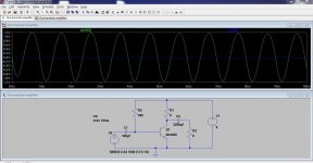
The sinewaves are a lot different than they were before! hanging around in the middle between on and off 
but it moves the subwoofer forwards (outwards) and backwards (inwards) this time around!
and I'm not using a darlington transistor... I checked it's a normal transistor I got from a broken TV motherboard
and I checked it on the data sheet its only a single transistor not a darlington!.. yikes!!
I'm looking for a specific transformer to reduce the DC going to the output
is there one that can work for a 4ohms subwoofer?
it is 4ohms 175 watts rms 500 watts max
and it is a DUAL brand it's cheap but hits hard enough for me
or is there another way to reduce the DC using something other than a transformer?
Last edited:
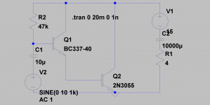
Yes, this version phase inverts the signal. Use of a single transistor rather than a darlington means the input impedance is very low and the coupling cap at the input needs to be big.
You have a lot to learn on amplifier design A transformer used as the collector load would work but it would have to be purpose built. You won't find one for this.
No, the way forward is to look at simple multistage amplifiers that use capacitor coupling. That could be done with a one transistor amp but it would be inefficient.
You have a lot to learn on amplifier design
A transformer used as the collector load would work but it would have to be purpose built. You won't find one for this.No, the way forward is to look at simple multistage amplifiers that use capacitor coupling. That could be done with a one transistor amp but it would be inefficient.
Attachments
wow that's terribly inefficient compared to mine
I tried using a turdly transformer used in a AC to AC power supply but it didn't have the output/input voltage and ohms and whatnot that I need to get proper power out of my subwoofer...
isn't there some audio transformers that are made for this job? couldn't someone direct me to a website that shows what I would need? I mean surely there's someone on the planet that has an audio transformer that's made for this job!
unless its better to just try the capacitor thingy how would I go about doing that?
i'm curious but idk how to do it.
Last edited:
I don't have one of those that big.... do you mean 470uf? or 4700uf? and I've already tried a bunch of different combinations of capacitors in series with my speaker and every time I try I get absolutely no sound out of my speaker whenever I wire a capacitor in series with the speaker
I don't have one of those that big.... do you mean 470uf? or 4700uf? and I've already tried a bunch of different combinations of capacitors in series with my speaker and every time I try I get absolutely no sound out of my speaker whenever I wire a capacitor in series with the speaker
You won't get sound wiring it just in series. Look at my diagram above. You need a collector load resistor (R1) and to take the audio from that via the cap. 4700uf would be typical for a large speaker but anything above 470uf will work OK to test it.
fun
hi
mine is better, efective full class B with zero idle
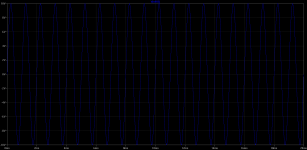
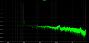
but ac sims show hf oscillations
The mk2 version. And it works... sort of. (we think the transistors a darlington if I remember correctly)
realflow100, there is one fundamental difference between this amp and your first. Can you see what it is ?
hi
mine is better, efective full class B with zero idle
but ac sims show hf oscillations
Attachments
I can't see Realflow's version.
Where is the link to his schematic?
This was the original as far as we know,
http://www.diyaudio.com/forums/soli...working-transistor-amplifier.html#post3179356
we deduced the circuit from the point to point wiring description.
Do you not see the circuits in post 17 and 22 in this thread Andrew ? They are as close as we can get from the descriptions.
hi
mine is better, efective full class B with zero idle
but ac sims show hf oscillations
What are you trying to show with this ?
Hmmm still nothing out of my speaker when I have the resistor and capacitor wired up like that.... am I putting them in the wrong place? where do they go exactly?
They have to go like I showed in post #22
Resistor R1 is the load resistor for the transistor. Resistor R2 has to be chosen so that the voltage on the collector is around half of the supply voltage. This allows the voltage to swing equally up and down and gives maximum output voltage swing. Also this resistor value will be different for every transistor and is a major limitation of the simple design. Resistor R3 is the speaker.
thanks for the link.This was the original as far as we know,
http://www.diyaudio.com/forums/soli...working-transistor-amplifier.html#post3179356
we deduced the circuit from the point to point wiring description.
Do you not see the circuits in post 17 and 22 in this thread Andrew ? They are as close as we can get from the descriptions.
Yes, I can see those sims with their schematics. But I thought they were your amplifiers. I could not see any sch from realF.
I'm still confused on exactly where to put them... between which positive or negative and which emitter collector or base or other positive or negative?
sorry i'm such a noob still I'm still learning!
oh and I hooked up the 12 volt power supply and it bumps my subwoofer showing at least half inch excursion it's insane everything in my house is vibrating like crazy
it's showing what looks like at LEAST 25-55 watts!!
but the transistor gets super super hot (it almost burns my finger if I touch the top of the transistor but it doesn't burn my finger ... its just really super hot.... but I let it cool down for an hour so it doesnt burn out... I don't want to ruin my amplifier!
I'm totally confused on how to remove the DC from it without using a transformer...
Hi,
Reality will bite at some point and the nonsense in the thread title and OP become apparent.
Download this free emulator : SPICE-Based Analog Simulation Program - TINA-TI - TI Software Folder
And use it to post your schematic. Also post the Tina file for your schematic and some
kind soul might show you what it actually does (and doesn't) do, and how to modify it.
rgds, sreten.
Last edited:
Okay I'll try that thanks
by the way I managed to run my amplifier off of salt and water battery!! (one single cell!)
it's a lil quiet but it actually visably moves my subwoofer! it doesn't put out more than one volt though but it still works!!
I can even run my amplifier off of a single capacitor. (it actually works slightly)
if I simply touch the power wires together I get a little static crackle but no real sound.
but if I just simply put them to a capacitor or in a salt water battery it really increases the power and actually amplifies my sound a bit!
really neat! a home made battery and a home made amplifier... together! that's new!
I'll see about the schematic now.
Hi,
I also found a 14MB version of "The Art of Electronics 1989 djvu file"
on a well known site, you'll need this free reader though to read it :
Free DjVu Reader | PDFlite
(I suggest declining all the optional installs it suggests).
My favourite book by a long way on the basics of electronics.
rgds, sreten.
search for "The_Art_of_Electronics_2ed.djvu"
Last edited:
okay here's the schematic I drew up
Also it doesn't show the values because I don't know the values.
I only know the value of the capacitor going to the input so that's all i put in it.
It's not a working circuit in the program
all I did was just draw it out so I'm not sure whether it works in this circuit or not.
but it works in the circuit I made my amplifier in the real world.
this just gives a quick simple example of how I have my circuit wired up.
Attachments
- Status
- This old topic is closed. If you want to reopen this topic, contact a moderator using the "Report Post" button.
- Home
- Amplifiers
- Solid State
- I just designed an amplifier to power big speakers with small voltage!