Skip the so-called current mirror with MOS-FET from VAS because is not useful. Or does not have the same benefits as one with BJT's. If you do not believe me, then try and convince you.
Then, why use MPSA42? Try my solution where you can use instead of 2N6800 any equivalent Hitachi part or IRF610 from Samsung. And includes some constant current source in the circuit input and VAS as we have done it.
It's much better this way if you want to get some performance, because otherwise, as you drew you amplifier diagram, the results are in performance of BJT's classic. I guess the solution with MOSFET you want to achieve much higher performance variant BJT. Right? If yes, then follow my advice.
Hello Petru
First of all thank you (multumesc) for the advise!
Of course I want performance, otherwise no reason to do anything with these circuit even if I have those devices.
To me not all the way clear what you write (I know you want to help) but we have to go step by step over the circuit.
I think I have some IRF610 at home, so I can count on it.
You can write PM to gaborzoltan2@gmail.com
Also anybody who want PM me please feel free.
Thank you
Greetings Gabor
Several mod was done
Hello Petru
Sorry about the previous post, I really did not had time to think on your advise.
I was in hurry to the church but I wanted to write so not to appear I ignore your help!")
Now I had more time and went over on the circuit. I think (if I understood well)you advised something like these.
I put several question marks because I have no idea what would be right value for those part, for those resistors, diodes and do I use Hitachi or the more avaleble IRF mosfet or somethig else.
Can you help with those please?
Also If I made a mistake how I draw the new circuit please let me know.
Now do the 470R trimmer will be OK? Or I must go back to 2.2K originaly it was.
Would you like if I ad a BJT between that trimmer and the 330R resistors like you did (MJE340)
Thanks one more time for your help!
Greetings Gabor
Hello Petru
Sorry about the previous post, I really did not had time to think on your advise.
I was in hurry to the church but I wanted to write so not to appear I ignore your help!
Now I had more time and went over on the circuit. I think (if I understood well)you advised something like these.
I put several question marks because I have no idea what would be right value for those part, for those resistors, diodes and do I use Hitachi or the more avaleble IRF mosfet or somethig else.
Can you help with those please?
Also If I made a mistake how I draw the new circuit please let me know.
Now do the 470R trimmer will be OK? Or I must go back to 2.2K originaly it was.
Would you like if I ad a BJT between that trimmer and the 330R resistors like you did (MJE340)
Thanks one more time for your help!
Greetings Gabor
Attachments
Last edited:
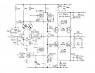
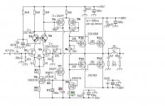
I have attached below the new amplifier diagram you posted above, where we numbered component values (only those which are necessary in discussion).
Trimmer's value is determined taking into account two things:
- VAS circuit current value;
- The desired setting the idle current.
Current in VAS is determined by mathematical formula:
I_vas = 0.8 * Uzener_D2 / R3
or, whether, it requires a current of 5mA then we find the value of R3:
R3 = 0.8 * Uzener_D2 / I_vas
Suppose you chose a zener diode of 15V when R3 is:
R3 = 0.8 * 15 / 0.005 = 2400 Ohm or 2K4
Resistor R2 is determined by a similar way provided to choose an electric current that is supported by J-FET transistors. For example 2SK117 are three types according to the classification of IDSS:
Y: 1.2 ~ 3.0 mA, GR: 2.6 ~ 6.5 mA, BL: 6 ~ 14 mA:
Let's say you choose 2.5mA:
R3 = (0.8 * Uzener_D2 - 0.7) / I_vas
R3 = (0.8 * 15 - 0.7) / 0.0025 = 4520 Ohmi or you can choose standard value 4k7.
Diode D1 can be a common switching diode, 1N4148 or 1N4935 type.
Then capacitor C1 can be shown theoretically that can range from 10uF and 100uF.
And finally, the Rt value Trimmer. To determine this value must know opening voltage transistors T10...T13. I do not analyzed the data sheet 2SK134 / 2SK1057 but you can resume calculations applying the following formula:
Rt = Vt / I_vas
Suppose that for an idle current of 200mA opening a voltage is 8V final pair, then:
Rt = 8 / 0.005 = 1600 Ohm. You can choose in this case one trimmer about 2K.
Attachments
Last edited:
Hello
Thank you so much!!!
I have another important question
Because now we have T8 the 33K resistor no longer good there.
The zener diode was reduced from 20V to 10 before the constant current source and the resistor value was increased from 6.8K to 30K.
I see you use 2X20K but a bit higher value zener. 1X30K no way to be good there. How much current flow true that resistor because you use 3PC? What do you think between 6.8K and 8.2 2W?
For T8 IRF610 or 2SJ77?
Some information
I have a 40-0-40VAC about 750-800VA transformer. That would give around 52-54V under these load.
For the front I will use at least 10V higher rail voltage like on the power stage.
I want to bias each channel about (total bias) 200mA. I'm not sure the transformer can take more. I use one transformer for both channel.
The 2SK170BL I plan to use. The BL grade IDSS between 6-12mA very similar than the 2SK117BL.
I think I have 2SK117 to but I'm nut sure the grade. I will stick with the 170BL. That is more popular.
I do like your amplifier a lot, If it would be lateral I would go on and build it.
Now these one became very close to yours. Thank you and thank you!!
Greetings Gabor
Attachments
Last edited:
Hello
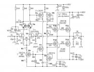
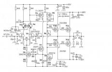
I upgraded the circuit once more thanks to Petru!
The red underline parts still questionable or need to be calculated.
I post the circuit if someone interested on or has more some fine idea..........
I think now these close to get tested.
Unfortunately I never run sim on amplifier circuit, usually I build it in real life to get some idea about the sound and how it will work.
Thanks one more time for the HELP!
Greetings Gabor
Attachments
Last edited:
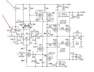
A big current IDSS means a higher probability of noise in the input stage. So BL series is not the best choice. It would be good to look series Y.
HZ10 diode voltage is too low and will work J-FET's with a voltage of less than 10V, about 9.35V (so it will saturate faster, is not good). Choose zener diode of 15V or 18V.
R1 = 2k2 has a critical value. A value too high will reduce the effectiveness of CCS (constant current source made with T8), one value too low will increase noise in the input stage (including the EMI influence, "in an indirect way"). Depending on the voltage of the amplifier, saturation voltage of the transistor from CSS and electric current CSS, you need choose one resistor, initially following a theoretical calculation, then after some experimental tests. Theoretical calculation is based on the hypothesis of a voltage difference on that resistor, which is not greater than the voltage UDS J-FET transistor. I recommend it to a voltage difference of about 10V (I rate this voltage with Vcss).
If the current CSS is I_css = 0.0025A (as I said above - there I used as reference in calculating all R3 = 4520 Ohm, but is wrong... typo mistake.. is R2 = 4520 Ohm), then R1 will be:
R1 = Vcss / I_css = 10 / 0.0025 = 4K
Again, the new value R1 will be tested experimentally.
Last edited:
Performances of this amp is globaly not better than the goldmund
iteration that was once popularized in this site wich used a bipolar
VAS and that s not by chance since it allow better perfs than
a mosfet inspired one.
Set aside this comparison , the amp has basicaly constant
distorsion in function of frequency , lower than 0.01% at mid power.
And if the threshold voltage is at most 2.2V for 100mA , what must be
the value of the trimmer resistance.?....
And how will it saturate ?...
As already said , excess current , wich is the parasitical
current from drain to gate , will increase exponentialy above
8 to 9V , hence linearity will much decrease.
iteration that was once popularized in this site wich used a bipolar
VAS and that s not by chance since it allow better perfs than
a mosfet inspired one.
Set aside this comparison , the amp has basicaly constant
distorsion in function of frequency , lower than 0.01% at mid power.
And finally, the Rt value Trimmer. To determine this value must know opening voltage transistors T10...T13. I do not analyzed the data sheet 2SK134 / 2SK1057 but you can resume calculations applying the following formula:
Rt = Vt / I_vas
Suppose that for an idle current of 200mA opening a voltage is 8V final pair, then:
Rt = 8 / 0.005 = 1600 Ohm. You can choose in this case one trimmer about 2K.
And if the threshold voltage is at most 2.2V for 100mA , what must be
the value of the trimmer resistance.?....
HZ10 diode voltage is too low and will work J-FET's with a voltage of less than 10V, about 9.35V (so it will saturate faster, is not good). Choose zener diode of 15V or 18V.
And how will it saturate ?...
As already said , excess current , wich is the parasitical
current from drain to gate , will increase exponentialy above
8 to 9V , hence linearity will much decrease.
You mean 2.2V between grid MOSFET's from the the positive and negative power rails? This 2.2.V seems rather small for a power MOSFET. especially if you want a current of 200mA idle! However, the formula remains the same considering the current through VAS about 0.005 A:Performances of this amp is globaly not better than And if the threshold voltage is at most 2.2V for 100mA , what must be
the value of the trimmer resistance.?....
Rt = 2.2 / 0.005 = 440 Ohm.
And how will it saturate ?...
As already said , excess current , wich is the parasitical
current from drain to gate , will increase exponentialy above
8 to 9V , hence linearity will much decrease.
I said saturate faster to the same input signal comparative with case when the voltage Uds would be more than 10V. For example, my project DP400 requires the input of a voltage 1.8Vrms to charge nominal power. If you use the J-FET with a voltage less than 10V Uds, it can not ensure a proper trip to other transistors saturation voltage, so will tend to increase the THD close to the nominal power, at a slightly higher value in the circuit input and overall the whole amplifier. These small technical quibbles are difficult to spot and deserves taken into account as long as we want them to squeezing as much performance from the amplifier.
!!! Some technical terms in Romanian with hard to find a corresponding 100% correct in English, therefore, some of the expressions used might not have exactly the right connotation.
Performances of this amp is globaly not better than the goldmund
iteration that was once popularized in this site wich used a bipolar
VAS and that s not by chance since it allow better perfs than
a mosfet inspired one.
QUOTE]
Hello
Thank you once more for both of you!!
wahab
Do you suggest if we change the VAS to bipolar (it will allow) we will get better performance??
We can test it, because I have those Hitachi devices or because originally was used fet for VAS not necessary to stick with that.
Performance more important.
For the front I want to stick with JFet.
I did used in my Darlington amp BC550/560, after I switch to 2SJ74BL/2SK170BL and I got a huge improvement!
Also in the SymaSym Mike replaced the MPSA18 with 2SK170BL and did improved the sound.
I did tested on my Symasym and really was better than the BJT.
donpetru
The best I can come up to get lower IDSS that would be GR grade JFet.
2SK170GR very popular among RIAA builders. Low noise devices.
Similar than the 2SK117GR.
2SK170GR still available in many stores. I have at home so I can start the test with that.
Please let me know your opinion on these!
Thank you sir!
For Rt we can go with 2K and after the first bias set up I can measure
the trimmer resistance and lower the value if it need to be (or if lower value behave better)
I will do those change you advised earlier!
HZ10 will be replaced with 15V..
I will go over on your post again and upgrade the circuit.
Thanks one more time!
-To think about GB now is way to early. Even after we get a certain performance (we satisfied with the sound) it would be useful some other guy build the amp to to get back more performance report.
Greetings Gabor
I said saturate faster to the same input signal comparative with case when the voltage Uds would be more than 10V. For example, my project DP400 requires the input of a voltage 1.8Vrms to charge nominal power. If you use the J-FET with a voltage less than 10V Uds, it can not ensure a proper trip to other transistors saturation voltage, so will tend to increase the THD close to the nominal power, at a slightly higher value in the circuit input and overall the whole amplifier. [/COLOR]
This amp use negative feedback so the Jfets need only 100mV
variation in their drain voltage to correctly make the VAS swinging
the full rail voltage, hence the latter provid most of the gain.
That s about 1% of the 9.6V VGS provided by a 10V zener
in the cascode, wich will be hardly a limiting factor.
If you choose 2SK170GR then every J-FET will be polarized at a current of approximately 3 mA, which means a total current of 6mA for CCS on the input. In this case, change the values of R1 and R2 as follows:
R2 = (0.8 * Uzener_D2 - 0.7) / I_vas, where I_vas = 0.006 A.
R2 = (0.8 * 15 - 0.7) / 0.006 = 1833 Ohm - you can choose 1k8
And the value of R1 will be:
R1 = Vcss / I_css = 10 / 0.006 = 1666 Ohm - choose a default value of 1K5 or 1k6.
Again, attention to the current input circuit; 6mA current is quite large - using a popular expression - can gather a lot of noise but worth trying.
Let us know here on the experimental stage of this amplifier, some opinions, after the first version of the prototype. Then will apply improvements that will be necessary. Good luck.
Later edit: @wahab, I understand your point of view. It's a good point.
Last edited:
Again said:Later edit:[/B] @wahab, I understand your point of view. It's a good point.
Hello
donpetru
Thank you once more
!GR IDSS rating 2.2 to 6mA, I will pick the lowest matched 2PC I have.
I upgraded the circuit after the advised value
I still need some value for start for D2, for R3 if I remember well you wrote 4K7 is wrong value
Do I keep HZ15V or go back to 10V?
@wahab, I understand your point of view. It's a good point
I added a input capacitor, I will start with 4.7uF after the test (I'll hear the amp (sound)tone) I will decide about that.
I will work on the layout so I can start testing what we have now.
I'll buy the missing parts (resistors and diodes) tomorrow.
Thank you for the help to all of you!
Greetings Gabor
Attachments
R3 = 2k4, as I said here:
http://www.diyaudio.com/forums/soli...mplifier-diy-designed-paul-kemble-naim-5.html
In that post I wrote wrong only this part:
Now, replace the part above from quote with this:
Concerning D2, I quote below what I said in a previous post when I determined R3. So, diode D2 wil be 15V zener.
http://www.diyaudio.com/forums/soli...mplifier-diy-designed-paul-kemble-naim-5.html
In that post I wrote wrong only this part:
Corrected should look like this:Let's say you choose 2.5mA:
R3 = (0.8 * Uzener_D2 - 0.7) / I_vas
R3 = (0.8 * 15 - 0.7) / 0.0025 = 4520 Ohmi or you can choose standard value 4k7.
So, it was only mistake notation R3 ---> R2.Let's say you choose 2.5mA:
R2 = (0.8 * Uzener_D2 - 0.7) / I_vas
R2 = (0.8 * 15 - 0.7) / 0.0025 = 4520 Ohmi or you can choose standard value 4k7.
Now, replace the part above from quote with this:
R2 = (0.8 * Uzener_D2 - 0.7) / I_vas, where I_vas = 0.006 A.
R2 = (0.8 * 15 - 0.7) / 0.006 = 1833 Ohm - you can choose 1k8
Concerning D2, I quote below what I said in a previous post when I determined R3. So, diode D2 wil be 15V zener.
Current in VAS is determined by mathematical formula:
I_vas = 0.8 * Uzener_D2 / R3
or, whether, it requires a current of 5mA then we find the value of R3:
R3 = 0.8 * Uzener_D2 / I_vas
Suppose you chose a zener diode of 15V when R3 is:
R3 = 0.8 * 15 / 0.005 = 2400 Ohm or 2K4
Layout is ready
Hello
Just finished the layout for the amplifier.
So soon I can start test her.
I draw with my computer paint program so I use color code for the parts.
Red- mosfet, JFet, transistor
Green- resistors
Blue- capacitors
Grey- trimmers
Yellow- jumper
Purple- diodes
So here is it if someone interested, the layout not tested yet but I drew more than a dozen of layout like these, 99% work at first.
Greetings Gabor
Attachments
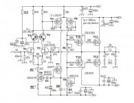
Before building this amp , a few points that matters if black smoke
is not the goal...
The biaising trimmer should be about 500R , as already pointed ,
if you use Renesas/Hitachi laterals wich have low Vth.
It seems that there is two critical flaws in the schematic.
The first is that the VAS current source as well as the differential current
source voltage reference , D2 , is fed by one leg of the differential VAS ,
wich is surely a mistake in the schematic.
Second , the differential fet current source has a diode , D1 , in serial with its
gate that is placed the wrong side.
Last edited:
- Home
- Amplifiers
- Solid State
- All Hitachi Lateral Fet amplifier for DIY described by Paul Kemble