Hard to believe so little interest on these amp circuit
That's because you cannot build an amp. If you can, you may also have little interest on the amp.
Some might have discarded the idea simply from looking at the VAS.
Some might have discarded the idea after doing some simulation.
Some might have discarded the amp after building and listening to it.
If you want to listen to all fet amp, go to Lineup thread or Fetzilla.
Please don't write these (I ask kindly) I built or tested over 100 amplifier some with my own mod , PC boars design etc.That's because you cannot build an amp. If you can, you may also have little interest on the amp.
If I had little interest on the amp I do not start these thread!
Some might have discarded the idea simply from looking at the VAS.
What is wrong with the WAS? Let s fix it, that is why DIY..
Some might have discarded the idea after doing some simulation.
Simulation and reality is two different think. Not to write about the sound!
Some might have discarded the amp after building and listening to it.
If I build a amp and sound bad at least I would warn other DIY-ers NOT TO BIULD sound bad, not working etc.
I assume you to, or not?
Please do not take it personal criticism, I have nothing against you..
All my respect to all fellow DIY-ers.
Why I like these circuit? Not very often see on the forum all (lateral) fet schematic!
One think I would like to ask, if you think these or that is wrong in the circuit please let us know why and how would you fix it!
It would be much more positive than just these no good or that
Some advise would be more constructive than criticism even if that sound positive...
Greetings and thank you for all of you for the comment!
Gabor
Last edited:
@gaborbela, and other users here, I notice that you ignored my remark in a previous post. What you want to do or has done design from Naim, I began to conceive through 2003.
To figure out what is wrong with amplifier diagram posted by you and made from designer to Naim, I recommend viewing below attached project designed by me. DP400 is a project I started when I was in college and during this topic, I thought I outline a final revision. Initials project name is my name.
And please, do not ask me about PCB.
Attachments
@gaborbela, and other users here, I notice that you ignored my remark in a previous post.
What you want to do or has done design from Naim, I began to conceive through 2003.
And please, do not ask me about PCB.
No I do not ignore no body's remark just it would be nice to be constructive like these post of yours!
To figure out what is wrong with amplifier diagram posted by you and made from designer to Naim, I recommend viewing below attached project designed by me. DP400 is a project I started when I was in college and during this topic, I thought I outline a final revision. Initials project name is my name.
Very nice design in did! To sad (to me only) not based on lateral fet. I did read many time Hex fet need high bias to sound good. Has to be biased in Class A..
I didn't tested so these based on another people opinion.
Greetings
Last edited:
Why I like these circuit? Not very often see on the forum all (lateral) fet schematic!
Some advise would be more constructive than criticism even if that sound positive...
Hehe... You asked why there is little interest. I just tried to give an accurate answer
My advise was to try the Fetzilla thread, for all FET amplifier.
Gabor, think about the truth or logic behind this:
Lateral fets are very expensive. You don't want to put it (two pairs per channel!?) in mediocre circuit.
The input cascode can use bipolars for the upper pair , cheaper and
performing as good if not better than the fets.
Keep the input fets , they can be replaced by recent ones.
There s no advantage on a all fet VAS , using bipolars would certainly
provide better perfs as well as getting rid of problematic availability.
The output stage , well , i wont say nothing about it , i m myself using
those very same laterals, although with a different topology.
Hello Jay
I would like to keep these as a high power amplifier, that is the reason for 2pair power mosfet.
Yes I did follow for a while the Fetzilla amplifier great design but how I stated I want higher power amplifier (I have 40-0-40VAC) transformer 700VA.
Yes lateral fets are expensive but sound great in a well designed circuit. It worth that extra cost.
We want to build great amps from cheap devices, I do not say not possible but to me worth that extra cost. I already have them. Renesans produce them $7/device I think that still affordable...
Welcome Zen Mod.
Welcome Wahab
I agree with you 100%! All do 2SK214/2SJ77 and similar fet still available and very good device
I will come up wit a new front end and WAS I hope I get help not negative or discouraging comment.
To exchange the was to bipolar probably I will need help there..
I will try may be we can go forward with these project.
Guys I want to learn, I do not think someone can say he didn't leaned nothing on the forum from other people.
Greetings Gabor
Last edited:
Hello wahab
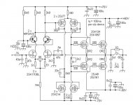
Is these acceptable for front end??
Greetings
Cant answer for the whole schematic but for the bipolar part of the cascode
increase the 6.8K resistor to 33K at least as the original value send
way more current than necessary to the zener.
This latter should be reduced to 10V max as it is the value
at wich the excess current start to increase dramaticaly
in most jfets.
Also , the MPSA18 are perhaps undersized in respect of TDP ,
a good replacement would be 2SA1360/2SC3423.
I once simulated this circuit to check its behaviour ,
i ll look at the data that are on an old hard drive ASAP.
Last edited:
Very similar circuit was in The Audio Amateur over 20 years ago by Erno. The MOSFETs in the middle are unobtanium, although you sometimes see them on EBay.
Recently there was 3 sets of lateral FETs for the 1980's Maplin mosfet amp on ebay.
Cant answer for the whole schematic but for the bipolar part of the cascode
increase the 6.8K resistor to 33K at least as the original value send
way more current than necessary to the zener.
This latter should be reduced to 10V max as it is the value
at wich the excess current start to increase dramaticaly
in most jfets.
Also , the MPSA18 are perhaps undersized in respect of TDP ,
a good replacement would be 2SA1360/2SC3423.
I once simulated this circuit to check its behaviour ,
i ll look at the data that are on an old hard drive ASAP.
Hello
Thank you wahab!
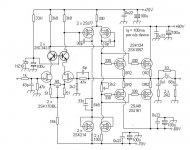
I made all the mod you advised.
I having second thoughts about the 2SC3423, do we really need that beefy bipolar for cascoding.
But I did changed because want to keep going forward so I can do some real life test.
I changed the resistor and the zener diode to.
When I did the first mod I drew the cascode both BJT reverse.
Hard to wait to see your sim result you have done.
I still believe there is a possibility to bring out a great amplifier from these circuit with some mod.
Thank you one more time.
Zen Mod I did look up the Marantz MA24 schematic I think that to complex.
I like as simple as possible until do not degrade the sound.
Thank you any way!
Greetings Gabor
Attachments
Hello Zen
Yes you right, it is really a nice amp specially seeing the end product.
I would like to build something around these simple circuit. Many amplifier designer got inspiration from the Hitachi circuit.
I think on the WAS (all do I have those fets) probably not the best idea how it is now.
Please keep follow the thread you always have great solution, great idea..
Greetings Gabor
I have a similar ciccuit banging around that has never been powered up fully (driver, yes - driver plus outputs, no), based on hot-biased MPF960 for the input stage - maybe I should dredge up that amp and finish it. The circuit was inspired by the original amp schematic in the Hitachi lateral MOSFET data sheet. I suspect that the inspiration for the Kemble circuit came from the same place, as the topology is similar.
Last edited:
Hello
Thank you wahab!
I made all the mod you advised.
I having second thoughts about the 2SC3423, do we really need that beefy bipolar for cascoding.
But I did changed because want to keep going forward so I can do some real life test.
I changed the resistor and the zener diode to.
When I did the first mod I drew the cascode both BJT reverse.
Hard to wait to see your sim result you have done.
I still believe there is a possibility to bring out a great amplifier from these circuit with some mod.
Thank you one more time.
I try to give you a few point that will help you understand
some of this amps requirements.
- The LTP total current is defined by the 16K resistor and will amount
to about 4.5mA so this resistor dissipation will be 0.315W , wich
is a lot , surely that it can be reduced without entailing the perfs
but if such a change is made the 3.3K resistors that load the cascode
should be increased in an inverse ratio.
The 16K could eventualy be replaced by a current source using
a 2SC3423 with a little heatsink.
- Each side of the cascode will have 2.25mA , hence the bipolar parts
will dissipate about 0.14W each , that s why i proposed the 2SA/2SC parts
wich can be replaced by their plastic case version 2SA1145/2SC2705
(used in the MA24 !!) although for reliability i would stick with the first ones.
- It is likely that the 2.2K trimmer has too high value for a VAS current
that is in the vicinity of a few mA to 10ma , a 470R would be more cautious ,
at least for the test board.
- If your output transistors are matched enough you can get
rid of the source 0.22R and expand the domain in wich the
output stage has a square law behaviour.
Hope this will be useful to your project.
Hello
Yes it help a lot!
I'm so grateful to you and some other guys who came to help not just write these or that bad, or please look for another amp.
About the Source resistors Juma once wrote those does not hurt if they used.
You 100% right if the power mosfet well matched better if the Source resistors left out.
Those are right before the speakers..
So reduce the 2.2K trimmer to 470R.
I'll stick with the transistor you told for cascode. For cascode I need only NPN device, or not???
Do I leave the WAS how it is now? Or let it test how is it and we will see.
If the sound to soft I think it will be better to use BJT..
When you find your sim. result please let us know.
I do have a amplifier to build (I have the stuffed PC boards) use almost the same devices but that is a symmetrical circuit.
Called Grand Mos
I post the basic circuit because that a commercial amp of Jean Marc.
Same lateral power mosfets , same mosfet as a driver and Toshiba J Fet cascoded with BC550/560
Symetrical circuit has a lot of disadvantage to. Can't be matched the P channel to the N channel not even close to 80%
Thank you
Greetings Gabor
Attachments
Last edited:
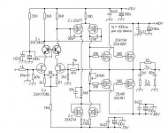
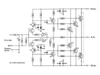
Skip the so-called current mirror with MOS-FET from VAS because is not useful. Or does not have the same benefits as one with BJT's. If you do not believe me, then try and convince you.Hello
Upgraded circuit.
Then, why use MPSA42? Try my solution where you can use instead of 2N6800 any equivalent Hitachi part or IRF610 from Samsung. And includes some constant current source in the circuit input and VAS as we have done it.
It's much better this way if you want to get some performance, because otherwise, as you drew you amplifier diagram, the results are in performance of BJT's classic. I guess the solution with MOSFET you want to achieve much higher performance variant BJT. Right? If yes, then follow my advice.
Last edited:
- Home
- Amplifiers
- Solid State
- All Hitachi Lateral Fet amplifier for DIY described by Paul Kemble