Hello wahab
You convince me about the ground! To get real picture at the test better to separate the ground (otherwise maybe the bad ground degrade the amplifier performance I will not get real picture)
I would like to ask a favour from you.
Can you mark on the circuit those connection to the ground which you think I should connect separate from the main ground.
I ask these because there will be several type of ground. 2 PS ground, signal ground etc.
Until now I built only one amp use 2 PS.....
Thank you very much!
I can ad one more ground trace outside the one already has, that will increase the size of the PC board less than 1Cm.
Also I can connect the two ground (where) if there need with a 10R resister.
Greetings Gabor
You convince me about the ground! To get real picture at the test better to separate the ground (otherwise maybe the bad ground degrade the amplifier performance I will not get real picture)
I would like to ask a favour from you.
Can you mark on the circuit those connection to the ground which you think I should connect separate from the main ground.
Also I can connect the two ground (where) if there need with a 10R resister.
Hi , Gabor
Here a schematic with the separated ground marked "HC ground" ,
there s only three components that use this ground , the zobel
network and the power stage decoupling capacitors.
All other components ground connection will be reunited in a second ground,
including the front end decoupling capacitors.
I ll do you a schematic of the power supply wirings , just tell me what kind
of transformer(s) you are using , either if this is one with all the necessary voltages
or if it s separate transformers for the front end and power stage.
I just try to test the amp now to get some idea of the performance.
I test the amp and after I'll start to upgrade. Even like these I can get some idea about the sound quality.
At the test I'll use only one PS how you advised. If I like what I'll hear I will increase the front end with 10V rail voltage.
I just each one PC board for test! After it will be easy to mode the PC board.
If I like the amp I want min. DALE or PRP resistors, and I'll upgrade the PC board to.
These only a test board, I don't want to mess with PP connection.
You can see that there s a current mirror as VAS load in the schematic below,
wich otherwise is strictly the same as in your PCB for all other parts.
Is it possible that you do your PCB routing such that both versions can use
the same PCB?
The change is very little , only a transistor is added and the two resistors
that enclose this added transistor could simply use some of the current version
VAS current source components holes.
The thing is that the amp behave so much better with a current mirror rather
than with a fixed current source as it allow symetrical and higher slew rate
while stability is better.
Also , it sets a very accurate balancing of the VAS transistors pair currents
and the amp has better linearity overall.
That s quite a lot of things considering that the component count is increased
by only a single transistor....
If you wants to make the best possible amp using this topology , such
an implementation has undoubtly way more impact on the amp quality than upgrading
it with selected components , provided the transistors are the good ones
and the resistors are rated to withstand the voltages , 125dB open loop gain
and induced high NFB will level the components differences , the transistors
linearity being the only remaining factor of importance.
Attachments
Hello wahab
Thank you very much for your help!
I will ad Q9 transistor to the layout. My question do I connect the HC ground with the other ground (with resistor of course)
I usually use a 10R resistor between the normal ground and the signal ground.
Because the speakers power goes from the HC do I take that ground from there?
I think yes because the Zobel network goes to the HC ground to.
About the PS I have 1PC 400-40VAC 800VA transformer(I think these would be under rated) or I use 2PC 39-0-39VAC 600VA transformers. For the front I have to look around what do I have. I think I have 45-0-45V transformer but that is from a power amp (huge size) ] Also I have to share the power transformers with another amplifier Aleph2 clone from Mr. Pass.
I will put the transformers in a separate enclosure and I use military connectors for each transformer to attach to the amplifiers until I get one more like these since right now I have 3PC.
These in case if I'd like both amplifier!!!
For the front end I will get something soon, until that I can test it only from one PS each channel.
I will post tomorrow some picture from the connectors and transformers.
Thank you one more time!")
Greetings Gabor
Thank you very much for your help!
I will ad Q9 transistor to the layout. My question do I connect the HC ground with the other ground (with resistor of course)
I usually use a 10R resistor between the normal ground and the signal ground.
Because the speakers power goes from the HC do I take that ground from there?
I think yes because the Zobel network goes to the HC ground to.
About the PS I have 1PC 400-40VAC 800VA transformer(I think these would be under rated) or I use 2PC 39-0-39VAC 600VA transformers. For the front I have to look around what do I have. I think I have 45-0-45V transformer but that is from a power amp (huge size) ] Also I have to share the power transformers with another amplifier Aleph2 clone from Mr. Pass.
I will put the transformers in a separate enclosure and I use military connectors for each transformer to attach to the amplifiers until I get one more like these since right now I have 3PC.
These in case if I'd like both amplifier!!!
For the front end I will get something soon, until that I can test it only from one PS each channel.
I will post tomorrow some picture from the connectors and transformers.
Thank you one more time!
Greetings Gabor
Last edited:
Some capacitor question
Hello wahab
I have some question about the next caps
For C4 16V will be enough?
I want to shave of from the existing ground trace, for the front I do not need 1Cm wide ground...
Another capacitor C5 at Zobel, usually we use 0.1uF. The 22nF it is a mistake or correct.
Size here does not mater because it will be mounted on the speakers terminal.
I did some work on the layout, I have to ad the HC ground and double check all and it will be done.
Right now is not finished!
It is possible to go regulated PS at the front in case I get higher voltage transformer.
These only after I test the amp.
Thank you very much!
Greetings Gabor
Attachments
Last edited:
I would take both the HC ground and the LC ground back to the Main Audio Ground.
But I would separate the Signal Ground with the attached NFB lower leg from the LC ground with that current reducing resistor & diodes.
C4 with the diodes in place should never see more than 1Vpk even during fault conditions.
Without the diodes C4 can see high voltages depending on which fault ocurrs.
You can use 5V caps, but 16V pre reformed is good insurance. That reforming is essential. Otherwise the cap oxides never properly form.
Last edited:
I will ad Q9 transistor to the layout.
Thank you for retaining this modification as not only it allow getting rid of
an annoying limitation that has been pointed from the start of this thread
by Zenmod but also to yield a better performing amp thanks to its use of the
subcircuits that have the best perfs returns and wich are rarely if ever used
all at the same time in amplifiers that borrow this topology.
My question do I connect the HC ground with the other ground (with resistor of course)
Yes , a 1R resistor will be adequate but still , each ground must have
its own wire going to the supply ground star point.
I repost the schematic with the resistor.
All grounds with the earth sign are connected to the LC (Low Current) ground.
The second schematic is the one of the PSU so you understand better
how all theses troubling earths are connected.
Because the speakers power goes from the HC do I take that ground from there?
The speaker ground is to be taken on the PSU ground star point not
from the amp PCB grounds.
I think yes because the Zobel network goes to the HC ground to.
If mounted on the PCB the zobel network ground goes to the HC
(High Current) ground , otherwise if it s mounted near the speaker
connector it can then simply use the speaker ground wire.
About the PS I have 1PC 400-40VAC 800VA transformer(I think these would be under rated)
I guess it is a 2 x 40V AC/800VA transformer , in wich case it s not
underated , quite the contrary , it is overated...
A 500VA transformer is largely enough for 8R speakers and even for 4R
if the amp is not at 100% max power 7/24 so 800VA is powerfull enough
to withstand permanently full power on 4R.
I have some question about the next caps
For C4 16V will be enough?
As pointed by Andrew 16V is largely enough but his 6V figure is not....
Another capacitor C5 at Zobel, usually we use 0.1uF. The 22nF it is a mistake or correct.
22nf should work well enough , i have two amps using three lateral pairs
and one has 22nf while the other is happy with 15nF.
Size here does not mater because it will be mounted on the speakers terminal.
As pointed above , in this case its ground connection can use
either the speaker ground wire or be returned directly to the power
supply ground star point.
It is possible to go regulated PS at the front in case I get higher voltage transformer.
It is possible but not strictly necessary as the amp has high open loop gain ,
hence rejection of the supply noises is operated by the amp inherent
high negative feedback efficently enough that a 47R + 1000uF decoupling
cell for the front end is all what is needed to render a regulated power
supply useless.
On the schematic i did put 220uF , this is the absolute minimal value for
these front end decoupling caps.
I saw that you did parralel them with small MKP/MKT capacitors and it is
a very good thing in respect of the PCB high frequency behaviour.
Hope this will help remove eventual shadowed areas....
Attachments
Last edited:
I guess it is a 2 x 40V AC/800VA transformer , in wich case it s not
underated , quite the contrary , it is overated...
A 500VA transformer is largely enough for 8R speakers and even for 4R
if the amp is not at 100% max power 7/24 so 800VA is powerfull enough
to withstand permanently full power on 4R.QUOTE]
Hello
A big thank both of you for the help!
About the transformer what is troubling me.
The Grand Mos use 52V rail voltage, biased 400mA / channel. 2PC 500VA transformer minimum req.
It use 3 pair power mosfet like us. If I divide that bias 3X a bit over 100mA / power mosfet.
We use 55V rail voltage, around 300mA bias/ channel (each power mosfet biased to 100mA)
My question the 800VA still will be enough to power both channel??? I use only 8R speakers!
If the answer YES that would resolve a great transformer issue for me!
The rest is clear to me.
The 1R resister will give enough filtering between the HC and LC ground?
I usually use 10R to separate the signal ground from the main ground.
To power both channel front from one transformer what would be the right VA rating?
I will have to purchase something. To feed the front must be 65V or I can go up 2-3V higher.
Easier to get a transformer when we have some tolerance. Otherwise I may have to order specially manufactured= which cost $$$..
Thank you one more time!
Greetings Gabor
Layout mode is done
Hello
Just finished the layout mod.
I have to go over to look for mistakes, but it should be OK how it is.
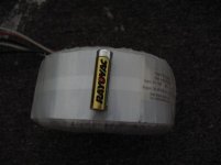
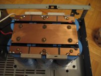
I did spread a bit more the power mosfets. All PC board got bigger a bit.
Here is the transformer you wrote it will do the job. That is a AA battery.
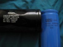
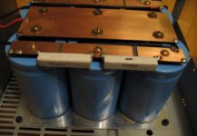
About PS capacitors I have 10PC Nippon CC 100 000uF, I don't know nothing about the quality since I never use those.
I can use 2PC Philips (those are great caps) and 2PC Nippon.
I know it will overkill but if does not degrade the sound I don't care.
I have 10PC Nippon 10 000uF 63V with solder lug type.
I will test which gave better result.
I do like large can capacitors if they are good quality, Philips, Mallory, Mepco, Cornel Dub. etc.
I did used these type successful in many Class A/B amp. 4PC set up as CRC .
Any opinion about PS caps?
Please do not forget to confirm the 800VA transformer will be good enough with 100mA bias/power device.
Greetings Gabor
Hello
Just finished the layout mod.
I have to go over to look for mistakes, but it should be OK how it is.
I did spread a bit more the power mosfets. All PC board got bigger a bit.
Here is the transformer you wrote it will do the job. That is a AA battery.
About PS capacitors I have 10PC Nippon CC 100 000uF, I don't know nothing about the quality since I never use those.
I can use 2PC Philips (those are great caps) and 2PC Nippon.
I know it will overkill but if does not degrade the sound I don't care.
I have 10PC Nippon 10 000uF 63V with solder lug type.
I will test which gave better result.
I do like large can capacitors if they are good quality, Philips, Mallory, Mepco, Cornel Dub. etc.
I did used these type successful in many Class A/B amp. 4PC set up as CRC .
Any opinion about PS caps?
Please do not forget to confirm the 800VA transformer will be good enough with 100mA bias/power device.
Greetings Gabor
Attachments
About the transformer what is troubling me.
My
Last edited:
Hello
Here is the black layout for these amp!
I do not say final because I'll go over once again to look for any errors.
I will let you know if I'll get any error!
I just found out I have a 6PC 30 000uF 75V capacitor bank Cornell Bubblier.
That should be good for the high power PS.
I have no need for those so I can use it here.
wahab I assume you didn't forget the bias when you calculated the transformer rating, so the 800VA will be OK.
Thanks one more time to everybody for the help and a big special thanks to wahab!
The next step to purchase the transistors and resistors, each the board and test it.
Now all look promising of course after the test I will know more!
Greetings Gabor
Here is the black layout for these amp!
I do not say final because I'll go over once again to look for any errors.
I will let you know if I'll get any error!
I just found out I have a 6PC 30 000uF 75V capacitor bank Cornell Bubblier.
That should be good for the high power PS.
I have no need for those so I can use it here.
wahab
I assume you didn't forget the bias when you calculated the transformer rating, so the 800VA will be OK. Thanks one more time to everybody for the help and a big special thanks to wahab!
The next step to purchase the transistors and resistors, each the board and test it.
Now all look promising of course after the test I will know more!
Greetings Gabor
Attachments
Last edited:
Hi Gabor ,
For some reason my previous post was badly edited.....
I ll put the text again since the page where i did edit it was still
opened and the text available by the same way....
This will make 600mA for the whole amplifier , that is (2 x 55V) x 0.6A = 66W ,
we are far from the available 800W...
Overall, such a transformer is largely within specs , it will never be used at its full
power even if the amp is 4R loaded.
At second thoughts not sure about this one....
In principle this resistor is not needed at all as both HC and LC have their
own returns to the star point so it is only here to provide a path to the zobel
network if ever one forget to connect the HC ground to the star point, hence
the low value of 1R, but if all is connected correctly this resistor becomes useless.
Just use what you have at hands , eventually you could add two windings of a few
dozen turns of 0.5mm2 to your toroids that will be connected in serial with the 40V windings ,
allowing to squeeze at zero cost the few volts that are needed for the front end higher voltage.
Such big caps are often more of a problem than a real advantage
as transient currents are huge when powering on but also when
charging the caps at each alternance , hence the PSU might
be noisier than with smaller caps...
Capacitors life expectancy and lifetime ability to work within their ratings
is mainly decided by the voltage and temperature at wich they are used.
In this respect , 63V caps do not suit the purpose , better less capacitance
and higher sustainable voltages and temperature than the opposite.
For total capacitance 2 x 20 000uF is a minimum.
Anything above 2 x 50 000uF wont bring anything substancial for this kind
of amp but it must differ with low feedback designs ,such as the Grandmos,
that have low power supply noise rejection.
For some reason my previous post was badly edited.....
I ll put the text again since the page where i did edit it was still
opened and the text available by the same way....
About the transformer what is troubling me.
My question the 800VA still will be enough to power both channel??? I use only 8R speakers!
If the answer YES that would resolve a great transformer issue for me!
To power both channel front from one transformer what would be the right VA rating?
This will make 600mA for the whole amplifier , that is (2 x 55V) x 0.6A = 66W ,
we are far from the available 800W...
Overall, such a transformer is largely within specs , it will never be used at its full
power even if the amp is 4R loaded.
The 1R resister will give enough filtering between the HC and LC ground?
I usually use 10R to separate the signal ground from the main ground.
At second thoughts not sure about this one....
In principle this resistor is not needed at all as both HC and LC have their
own returns to the star point so it is only here to provide a path to the zobel
network if ever one forget to connect the HC ground to the star point, hence
the low value of 1R, but if all is connected correctly this resistor becomes useless.
I will have to purchase something. To feed the front must be 65V or I can go up 2-3V higher.
Easier to get a transformer when we have some tolerance. Otherwise I may have to order specially
manufactured= which cost $$$..
Just use what you have at hands , eventually you could add two windings of a few
dozen turns of 0.5mm2 to your toroids that will be connected in serial with the 40V windings ,
allowing to squeeze at zero cost the few volts that are needed for the front end higher voltage.
.
About PS capacitors I have 10PC Nippon CC 100 000uF, I don't know nothing
about the quality since I never use those.
I can use 2PC Philips (those are great caps) and 2PC Nippon.
I know it will overkill but if does not degrade the sound I don't care.
I have 10PC Nippon 10 000uF 63V with solder lug type.
I will test which gave better result.
I do like large can capacitors if they are good quality, Philips, Mallory, Mepco, Cornel Dub. etc.
I did used these type successful in many Class A/B amp. 4PC set up as CRC .
Any opinion about PS caps?
Such big caps are often more of a problem than a real advantage
as transient currents are huge when powering on but also when
charging the caps at each alternance , hence the PSU might
be noisier than with smaller caps...
Capacitors life expectancy and lifetime ability to work within their ratings
is mainly decided by the voltage and temperature at wich they are used.
In this respect , 63V caps do not suit the purpose , better less capacitance
and higher sustainable voltages and temperature than the opposite.
For total capacitance 2 x 20 000uF is a minimum.
Anything above 2 x 50 000uF wont bring anything substancial for this kind
of amp but it must differ with low feedback designs ,such as the Grandmos,
that have low power supply noise rejection.
I just found out I have a 6PC 30 000uF 75V capacitor bank Cornell Bubblier.
That should be good for the high power PS.
I have no need for those so I can use it here.
Great, the voltage rating is high enough and it s always a relief
to usefuly recycle valuable parts...
wahab
Be assured that this transformer will enjoy a quiet and lazy life....
The next step to purchase the transistors and resistors, each the board and test it.
Now all look promising of course after the test I will know more!
According to simulations it s quite better than all other popular amps
using this topology without going into complexe additions such as error correction
or non switching circuitries , so i hope it will live up to your expectations.
Last edited:
Hello
Today I went over again on the layout, no mistake or error was find.
wahab I have a question to you
I see the R12 & R10 resisters in series, can I replace that two resister with one. I could use (fix up) that place on the layout....
Please let me know.
Thank you
Greetings Gabor
Today I went over again on the layout, no mistake or error was find.
wahab I have a question to you
I see the R12 & R10 resisters in series, can I replace that two resister with one. I could use (fix up) that place on the layout....
Please let me know.
Thank you
Greetings Gabor
Attachments
Hi Gabor,
You can use a single 68K 1 to 2W resistor instead but be aware that
the current through theses resistors is about 2mA when using a separate
higher voltage PSU for the front end , while the total voltage across them
is almost the full rail to rail voltage , about 125V , so the dissipation
will be about 0.25W , wich would be too high for 0.5W resistors , hence
i did put two in serial to reduce the burden to 0.125W per resistor
and the stress inflicted to the PCB as a single resistor , even if you take
a higher power one , will inevitably damage not only its own soldering
but also the PCB itself on the long term.
For testing the amp a single resistor can be used but for a definitive build
it would be better to use two resistors to ensure long term reliability.
post166:
I will suggest a very small, but what I consider to be a very important detail, in the grounding schematic.
The sch shows the star ground (Main Audio Ground - MAG) coincident with the junction of the smoothing caps.
I suggest that the MAG be moved just a couple of mm along the wire from the PSU Zero Volts plate.
An alternative is to bolt through the plate and tighten up a nut to secure the brass bolt to the plate. Attach the MAG terminal tags to the bolt and use a second nut to fix the MAG to the plate. This way the charging pulses across the plate do not influence the multiple and different physical connections that are on the "other side" of the first fixing nut.
Recently this has been discussed and the general conclusion is that this separation of PSU Zero Volts from the MAG is the better solution.
Hello
Thank you for the advise Andrew!
The ground will be somehow different since I separated the HC and LC ground on the board.
Now I got these transformer from Ebay to these project,(it was very cheap so I didn't wanted to pas by all do the shipping close to $20).
47.5V the right voltage I need to drive the front.
Big Toroidal Transformer 120V in 166VA 47 5V 19V 0 19V 47 5V 1 75A | eBay
Soon I will etch the PC boards (I need some P3A to) and I can start test it.
For the front what would be the min. capacitance requirement? like 4X 4700uF or I can use less (I have 2200uF 80V Nippon CC probably I'll need higher uF caps)
Thank you
Greetings Gabor
If your 4700uF are 100V just slap a single pair , it s more than enough ,
otherwise you can use your 2200uF , a pair of wich would also be adequate...
As for the front end transformer 160VA is overkill as the two front ends
will consume together 60 mA at most , that is 8 W , so a 22VA
transformer would already be at ease dealing with such little power.
otherwise you can use your 2200uF , a pair of wich would also be adequate...
As for the front end transformer 160VA is overkill as the two front ends
will consume together 60 mA at most , that is 8 W , so a 22VA
transformer would already be at ease dealing with such little power.
I need help with my transformer
Hello
I'm in trouble because the Ebay seller does not fund the transformer I purchased!
Quote:
Dear gabor222_---___,
Correct - I had it at one point. Again, the item has been misplaced in my inventory. I keep everything pretty meticulous so not sure how this happened, but I spent about 2 hours going through multiple times trying to find it. I'm sure you have lost something in your lifetime - and can understand. It's like when you go to the store, and the inventory system says they have something, but when they look on their shelves it's not there.
Again, sorry for the confusion. I refunded your money completely and immediately once I discovered the item was nowhere to be found.
Best, Ken
- usedstereoguy
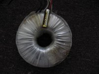
So I do started to ad some wire to my existing 2X40V transformer. To be 100% correct I added 10M wire.
I connected one side to the V continuously. Now when I measure it to the ground I get 15V only!
When I leave out the ground measure the the 2 white wire I get the 80V.
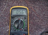
When i measure the opposite Voltage wire I get 56V see the pict.
In other word when I include the added wire I get only 56V instead 96V.
What is going on?
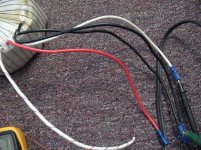
I include picture maybe someone can explain what is going on.
Wires
2 black 120V
White 40V, red center tap, other white 40V
I know 10M wire to much but now that second question.
Greetings Gabor
Hello
I'm in trouble because the Ebay seller does not fund the transformer I purchased!
Quote:
Dear gabor222_---___,
Correct - I had it at one point. Again, the item has been misplaced in my inventory. I keep everything pretty meticulous so not sure how this happened, but I spent about 2 hours going through multiple times trying to find it. I'm sure you have lost something in your lifetime - and can understand. It's like when you go to the store, and the inventory system says they have something, but when they look on their shelves it's not there.
Again, sorry for the confusion. I refunded your money completely and immediately once I discovered the item was nowhere to be found.
Best, Ken
- usedstereoguy
So I do started to ad some wire to my existing 2X40V transformer. To be 100% correct I added 10M wire.
I connected one side to the V continuously. Now when I measure it to the ground I get 15V only!
When I leave out the ground measure the the 2 white wire I get the 80V.
When i measure the opposite Voltage wire I get 56V see the pict.
In other word when I include the added wire I get only 56V instead 96V.
What is going on?
I include picture maybe someone can explain what is going on.
Wires
2 black 120V
White 40V, red center tap, other white 40V
I know 10M wire to much but now that second question.
Greetings Gabor
Attachments
Last edited:
You did a 24V winding and it is connected in antiphase with one 40V winding ,
hence when you measure the total voltage you will see a difference not a sum.
Just invert the ends of this cable and you ll see 64V when measuring from ground...
What is needed in fact is two 8V windings , about 26 turns each , depending
of your transformer , then connect one 8V in serial with a 40V one and you ll
have two 48V outputs wich will be connected to a separate bridge rectifier
and its dedicated caps.
The schematic below give an indication of how to procede with the added
windings.
Attachments
- Home
- Amplifiers
- Solid State
- All Hitachi Lateral Fet amplifier for DIY described by Paul Kemble