Hello
I successfully winded the transformer to have the necessary voltage to the front.
Thanks to Wahab!
I knew I connected something wrong because before I unwounded a transformer and I got the req. voltage.
Now I got 48.6V on both side. Each side needed 12 winding. So I took of half of the 10M wire I winded on and still it was enough to get these voltage.
Today I printed out the layout.
I did some minor mode and the printer has to be set up to get 174x74mm size(how it is with that frame)
Please use the paint program, printer set up 90%.........
I do post the final layout if someone interested on the amp to build it.
Before I built several symmetrical amps with lateral power mosfet. Like Zenquito, Profet, Grand Mosf (not tested yet)
At first I did like the Profet a lot. So I invested about $500-600 in Caddok resistors, EXICON, Class D mosfet orig Hitachi (because Renesans does not has the same sound quality, I tested) , PIO capacitors, pure silver wire etc. I wanted a Stereo bridged amp to get some extra power and extra dynamic.
Now when I spent that money (and built some BJT amplifier like my Darligton amp or NCC200 clone) I no longer like the sound of the Profet.
What a waste of money!
These should be different sound wise.
Hardly can wait to get the PC boards and components and start the tests.
Thanks one more time wahab!!!
Greetings Gabor
Attachments
Last edited:
Hello
What I wanted to write great to have these project (even I have to invest some to get the components) I can use those laterals I purchased..
These case not all my investment wasted.
I do believe (I hope based on wahab sim) these amp will sound better than those Symmetrical amps mentioned my previous post.
All do the Grand Mos was not tested yet I do not have much (interest) hope after the Profet or the Zenquito tests because these amps come from the same designer!
Not bad amps just not my taste, they are very speakers selective and some other reason ..
I feel lucky and happy to have these project, already had the heatsinks, transformer, matched power mosfets, JFes etc..
Greetings G
I successfully winded the transformer to have the necessary voltage to the front.
Now I got 48.6V on both side. Each side needed 12 winding. So I took of half of the 10M wire I winded on and still it was enough to get these voltage.
Hi Gabor ,
Can you post a schematic of your projected power supply.?
Such high voltages and avalaibles currents are of concern.....
Before I built several symmetrical amps with lateral power mosfet. Like Zenquito, Profet, Grand Mosf (not tested yet)
They have low intrinsical gain and consequently low ratios of NFB ,
hence they are more sensitive to the components quality but even
expensive parts wont compensate for the inadequacy of the front
ends in respect of the power devices driving requirements ,
so they will be easily outmatched by amplifiers using average parts
but high negative feedback ratios , wich is the case of this one....
Hello
Wahab I winded (connected) the transformer exactly how you advised.
The voltage measured is with out load! When I power up the amp I believe I will get the right voltage or less specially the 48.6V is in series with the 40V which will be loaded 300-350mA/channel.
If I take of one wind from the added 12 I get 47.5V or less. The wire must end on the same side where are the high power wires, also has to be outside because the mounting hardware.
Would you like a schematic from the whole PS or from the transformer?
Greetings Gabor
Hello
Wahab I winded (connected) the transformer exactly how you advised.
The voltage measured is with out load! When I power up the amp I believe I will get the right voltage or less specially the 48.6V is in series with the 40V which will be loaded 300-350mA/channel.
If I take of one wind from the added 12 I get 47.5V or less. The wire must end on the same side where are the high power wires, also has to be outside because the mounting hardware.
Would you like a schematic from the whole PS or from the transformer?
Greetings Gabor
A schematic from the power supply , that is how you re going
to connect the windings to the rectifiers.
The 40V windings must go to a 30A or so bridge rectifier
while the 47V windings goes to a 3 to 5A bridge rectifier ,
the capacitors of both rails using of course the 0V as common rail.
Hello
Yes wahab that is how I plan to connect it.
On the PC board I will test it both way. Using the resistor to separate the HC and the LC ground.
And I test it with out the resistor direct connected the LC ground from the front PS or I will test it I ad the resistor between the HC and LC capacitor ground.
Before I ad the 100nF cap just want to be sure you wrote about these Zener.
Not 100% part of the cascode (goes to the Base of the VAS)
Out of the list of the transistors the Toshiba 2SC3423 and complementary available on the best price.
Is that OK to be used everywhere? The Sanyo cost around 4X that much.
Thanks
Greetings Gabor
Attachments
Last edited:
Hello
Yes wahab that is how I plan to connect it.
On the PC board I will test it both way. Using the resistor to separate the HC and the LC ground.
Hi Gabor ,
Provided the HC and LC grounds are connected to the power supply ground
star point , wich is the good way to get rid of any noise running in the actual signal ground , this resistor become useless.
Before I ad the 100nF cap just want to be sure you wrote about these Zener.
Not 100% part of the cascode (goes to the Base of the VAS)
That s it , parraleled with this zener , it will forcibly be also
connected to the bases of Q8/Q7.
Out of the list of the transistors the Toshiba 2SC3423 and complementary available on the best price.
Is that OK to be used everywhere? The Sanyo cost around 4X that much.
They are within ratings and can be used instead of the Sanyo for both
NPN and PNP, there will be no difference as they are excellent devices.
I just want to warn you that Q7 dissipate 1.2W ,double the power
dissipated by Q8 and Q10 wich dissipate each 0.6W , while Q9 dissipation
is negligible , all the burden in this side of the VAS being beared by Q7 ,
hence its higher dissipation.
So make sure that Q7 has an adequate heatsink , moreover if it s thermaly
coupled with Q8 , wich will make 1.8W for the total amount of power dissipated
by a common heatspreader.
Hi Gabor ,
I just want to warn you that Q7 dissipate 1.2W ,double the power
dissipated by Q8 and Q10 wich dissipate each 0.6W , while Q9 dissipation
is negligible , all the burden in this side of the VAS being beared by Q7 ,
hence its higher dissipation.
So make sure that Q7 has an adequate heatsink , moreover if it s thermaly
coupled with Q8 , wich will make 1.8W for the total amount of power dissipated
by a common heatspreader.
Hello
Thank you
Yes I plan to use one a large TO220 heatsink on Q7 /Q8 and Q9 /Q10.
All transistor and J fet will be thermally coupled accept Q5/Q6 cascode transistors.
The J fet didn't came out face to face but I'll use silicon grease & heat shrink on them. Sometimes I used to use heat shrink and that hot glue.
Greetings Gabor
Q3/Q4 dissipate 0.075W each and need no heatsink while the input stage
current source Q11 dissipate 0.17W and should not need a heatsink although
i would put a very little one , something like a 1cm2 plate.
I updated the schematic with the added 100nF capacitors.
Also , i replaced the two diodes connected in parralel with C4
by two random transistors wich are used as diodes , each one
having its base connected to its collector , no need to update
your PCB since theses pins can be connected together directly.
Any small signal transistors will be adequate , just find a NPN
and a PNP in your devices trash bin , they do not need to be real
complementaries and their specs , set apart that the cheaper
the better , dont matter at all.
I add a schematic that show how the rectifiers are connected
to the transformer and will follow with some sims comparing this amp
with one wich has a nearby topology and is quite popular as "good sounding"....
Attachments

Hello wahab
I made the mode on the layout but I'm not 100% sure if is correct.
Please forgive me I'm very tired, can you take a look please.
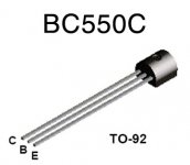
I use BC550/560 transistors, not face to face because that here isn't important.
I have another question
Can I use only 2PC capacitor in my amp power supply as efficient like 4PC CRC or CLC?
I have 4PC Kendeil capacitors 50V 50 000uF and I want to use them in a pair mono block (in my Darlington)
Now if two cap does not do as good job like CRC or CLC that case I have to purchase 4PC more. They are very expensive..
To use other type caps and degrade the quality of the Kendell that would be waste of money to.
I did built PS with two caps, it was not bad but I never compared with CRC or CLC type set up.
Actually the 2x50 000uF already over kill here.. I did purchased to use in my bridged ProFet clone, but that amp does not deserve to use those caps there because the Darlington sound that much better.
I see several good brand amp use only 2 large can cap in PS.
Greetings Gabor
I made the mode on the layout but I'm not 100% sure if is correct.
Please forgive me I'm very tired, can you take a look please
.I use BC550/560 transistors, not face to face because that here isn't important.
I have another question
Can I use only 2PC capacitor in my amp power supply as efficient like 4PC CRC or CLC?
I have 4PC Kendeil capacitors 50V 50 000uF and I want to use them in a pair mono block (in my Darlington)
Now if two cap does not do as good job like CRC or CLC that case I have to purchase 4PC more. They are very expensive..
To use other type caps and degrade the quality of the Kendell that would be waste of money to.
I did built PS with two caps, it was not bad but I never compared with CRC or CLC type set up.
Actually the 2x50 000uF already over kill here.. I did purchased to use in my bridged ProFet clone, but that amp does not deserve to use those caps there because the Darlington sound that much better.
I see several good brand amp use only 2 large can cap in PS.
Greetings Gabor
Attachments
Last edited:
dear sir,
plz also show me assembelled kit.
thanking you
Hello
Of course!
As soon as I start populating the PC board I will post pictures!
Greetings Gabor
Hello
Here is the layout I did include the last requested mode!
Yesterday I was very tired (not about the amplifier) the reason I do ask if the last mode is correct.
I'm sure it is correct.
Again if someone want to print out the layout please open it with the paint program, set up the printer (PAGE SETUP) 90% and that is the correct (right) size.
Any question you have about the layout I'll gladly answer it.
Thank again for the upgrade on the circuit!
Greetings Gabor
Attachments
Gabor have asked to have a few posts moved to other thread
http://www.diyaudio.com/forums/solid-state/133189-my-firs-diy-amplifier-20-years-go-5.html

moderation
http://www.diyaudio.com/forums/solid-state/133189-my-firs-diy-amplifier-20-years-go-5.html
moderation
Back to topic , some sims of the amp s expected caracteristics ,
with some comparisons with the much appreciated Goldmund Mimesis.
with some comparisons with the much appreciated Goldmund Mimesis.
Attachments
-
 SMALL SIGNAL BW.gif28.8 KB · Views: 380
 -
 LARGE SIGNAL BW.gif25.3 KB · Views: 351
 -
 GOLDMUND VS GABOR AMP THD1.gif42.7 KB · Views: 345
 -
 GOLDMUND VS GABOR AMP THD10.gif42.4 KB · Views: 117
 -
 GOLDMUND VS GABOR AMP IMD 0.4 + 7KHZ.gif44.1 KB · Views: 119
 -
 GOLDMUND VS GABOR AMP IMD 19 + 20KHZ.gif35.9 KB · Views: 120
 -
 GOLDMUND VS GABOR AMP SSB.gif28.5 KB · Views: 111
 -
 GOLDMUND VS GABOR AMP CMRR.gif30.6 KB · Views: 106
Hi Gabor,
Hope it will live up to expectations , that s somewhat of an extreme amp ,
the cascoded input stage + current mirrored cascoded differential VAS
structure has not been often used despite promising perfs.
Also , looking at a picture of your laterals , we can see that you have marked
them 0.88 or 0.89 , is it the gate/source voltage for 100mA current.?.
- Home
- Amplifiers
- Solid State
- All Hitachi Lateral Fet amplifier for DIY described by Paul Kemble