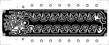
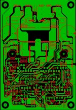
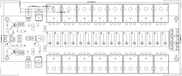
A lot of stuff looks fine, but here are some things you may want to consider:
I think there should be bypass caps, big ones in parallel with little ones, from R11-R1 junction to ground, and from R10-R16 junction to ground.
With all those output devices, you have to move a lot of charge at high frequency...it might be better to connect south end of R14 to top end of R15, but not connect the junction to the output. That would make for higher efficiency operation at high frequencies but reducing cross-conduction.
Maybe 1K in series with C12 would civilize the input impedance a bit, so the preamp doesn't have to deal directly with 220 pF.
Maybe C12 could be a film cap...my only concern with the electrolytic is that the polarizing voltage is pretty well not present.
Ditto the earlier statement about bias resistors R12 and R13 probably wrong.
Slew rate will be at best 10 V/us, a bit slow for an amp with rails so big.
Would be nice if Q1, Q7, Q8, and Q9 had room for emitter resistors, to allow for other solutions/tradeoffs on first stage current, slew rate, and compensation capacitors.
There's no SOA protection...perhaps with all those transistors, the fuse will die before the transistors do if you drive into a short.
It's sometime nice to have a little resistance between the emitters of Q6 and the bases of the output device. Same goes for Q5...often helps stop the emitter follower's tendency to parasitic oscillation.
I guess you'll mount Q4 to the output heatsink...you might still have to play with its tempco to keep the bias current calm.
C7 more typically would go from collector of Q2 to collector of Q3. As it sits, its actually a feature of sorts to split the drive...not sure if it's a good thing.
You probably want some small, e.g. high freq bypassing in parallel with the big (low freq)bypasses, both of which are missing, I guess as this is just a simulation.
Probably want an output inductor to keep things stable with capacitive loads. Might also need a Zobel network on the output.
That's all for now...
Update My Dynaco
Akitika GT-101
what is the use of c7?Hello
greetings anyone find any flaws in the schematic
warm regards
andrew lebon
- Status
- This old topic is closed. If you want to reopen this topic, contact a moderator using the "Report Post" button.
- Home
- Amplifiers
- Solid State
- SPAIN AMP


