hi
Just got this On a Higher Note :: M-800A Pure A Stereo Amplifier and i am surprised that each channel has 16 output devices per channel for 60W into 8 ohm. each device is 2SC5200 with its complimentary capable of 100w
Now for each channnel the ouput capacity is 6x100 W class A/B =600 Watt but the amplifier is rated at 60W per channel .
this leads to the question for diy that if i need to maintain a very strict linearity regime then why not parallel as many devices as possible ???? Improved damping factor, greater power handling ? Any warmth in sound ????
 that is a vere nice amp and very well made for sure.
my bad. Its not class A/B but clASS a.
Still that makes 60W/8 only 5.5Wx4=22W dissipation for a 100W transistor????? is it a simple way to improve SQ, i mean i intend to do this diy if 8 devices are asked to do the job of 2 and would simply improve SQ keeping every thing else the same,
Still that makes 60W/8 only 5.5Wx4=22W dissipation for a 100W transistor????? is it a simple way to improve SQ, i mean i intend to do this diy if 8 devices are asked to do the job of 2 and would simply improve SQ keeping every thing else the same,
Lanchile has given the reply that the amplifier can drive 1R loads. Think about how much more power it delivers at 1R than 8R and how much more dissipation will be necessary to allow that in class A. Then you may realise why you really need that many devices with high-end speaker drivers like ribbon tweeters.
Lower in the description we read "480W to spare". I think that's what it's all about. Funny, that's 8 x 60 = 480!
Lower in the description we read "480W to spare". I think that's what it's all about. Funny, that's 8 x 60 = 480!
Last edited:
my bad. Its not class A/B but clASS a.
Still that makes 60W/8 only 5.5Wx4=22W dissipation for a 100W transistor????? is it a simple way to improve SQ, i mean i intend to do this diy if 8 devices are asked to do the job of 2 and would simply improve SQ keeping every thing else the same,
60 watts at 8 ohms means that the amp is idling at 240 watts(one channel), assuming an efficiency of 25% so that 16 power tranies are each dissipating 15 watts each...no wonder the big big heatsinks....
i suspect that the classA rating goes for the 8ohm load only, other loads the amp goes into class AB...
anyone know the patent number for their "ODNF" - most amp circuit's aren't "smart" enough to recognize the "only distortion" part
I doubt they've really found a way around negative feedback realities - any system which uses one power amplification path to the output, controlled by some function of the input and the measured output is equivalent in principle to other negative feedback structures
the various local loop, nested loop, error correcting loop topologies that have been imagined, reinvented, given cute names all obey basic negative feedback theory with the attendent limitations and tradeoffs
and here's the source for that last paragraph
I doubt they've really found a way around negative feedback realities - any system which uses one power amplification path to the output, controlled by some function of the input and the measured output is equivalent in principle to other negative feedback structures
the various local loop, nested loop, error correcting loop topologies that have been imagined, reinvented, given cute names all obey basic negative feedback theory with the attendent limitations and tradeoffs
my mistake, shouldn't have added the comma
http://www.control.lth.se/~kja/modeluncertainty.pdf
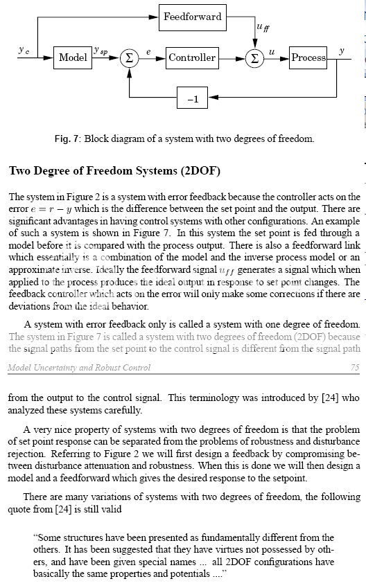
From K J Astrom “Model Uncertainty and Robust Control”
“fair use” excerpt:
Be sure to read that last para!
and here's the source for that last paragraph
The counterargument:
Hawksford/Cordell error correction is a 2 degree of freedom linear feedback control system,
All expressions of 2 degree of freedom control systems are equivalent.
Therefore Hawksford/Cordell error correction is equivalent to conventional error feedback with a command prefilter
Therefore the output linearizing disturbance rejection effect is exactly equivalent to error feedback and has the same gain-bandwidth/stability limits of ordinary 1 degree of freedom error feedback
A little reading: (slow to load, ~ 500K )
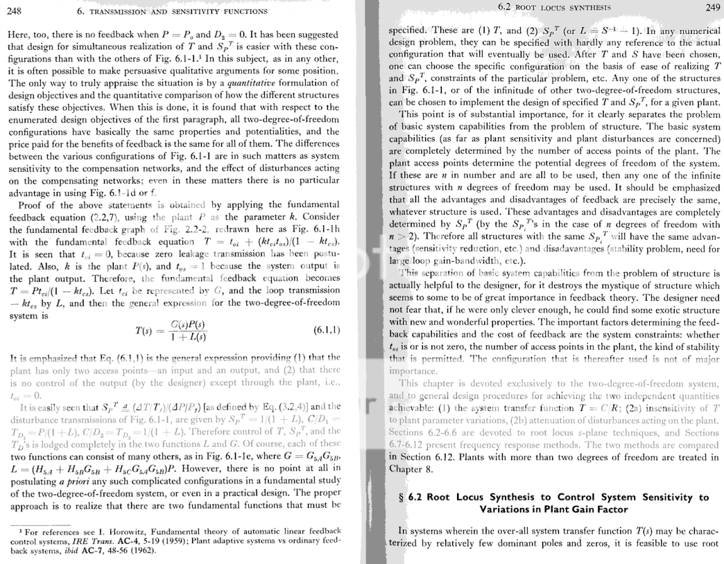
[I've referenced this a few time before in this thread I.M. Horowitz, "Synthesis of Feedback Systems" 1963 - that makes this a 40+ year old "controversy"]
I like Bob's circuit, I do think understanding it as a local feedback loop and tailoring its loop gain and frequency response is likely to be a good way forward
thanx for the lead to Only Distortion Negative Feedback Circuit
I still can't find a patent number - and the point of patents is that they can't be "secret" - you have to publicize the exact patent you claim is protecting your hardware or lose the right to sue for infringement
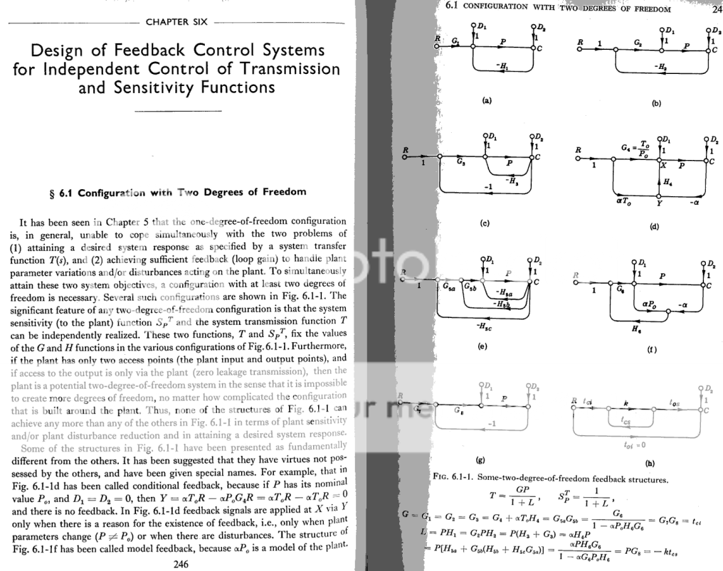
if the block diagram is correct representation of Luxman's ODNF then it is described by Horrowitz fig 6.1d “conditional feedback” graph – a topology dating back ~ ½ a century
I still can't find a patent number - and the point of patents is that they can't be "secret" - you have to publicize the exact patent you claim is protecting your hardware or lose the right to sue for infringement
if the block diagram is correct representation of Luxman's ODNF then it is described by Horrowitz fig 6.1d “conditional feedback” graph – a topology dating back ~ ½ a century
Attachments
The problem here is to set beta=1/(A*G), because A and G are the distorting entities.
If you would know exact what A and G were at all times you could compensate for it and have a distortionless amp.
But A and G vary with time, current, voltage, temp, from unit to unit etc so it is impossible to make beta=1/(A*G).
Edit: The result they give that (beta*K*G)/(1+beta*K*G)=1 implies that beta*K*G must be infinite.
But if K and/or G would be infinite, 'regular' feedback would already give a distortionless amp.
In fact, that equation is fundamentally the same as the equation for a 'regular' feedback amp Acl=Aol/(1+beta*Aol) and assuming that Aol is infinite.
jan didden
Last edited:
Hi Guys
The Luxman ODNF is nominally designed as a "zero feedback" amplifier. The main forward path is via linearised open-loop stages (free running) that drive one side of the output stage. A secondary path monitors the output DC and signal and drives the other half of the output stage. The output stage itself is four piars of complimentary BJTs plus drives, predrivers and bias. For the higher powered models, two or more output blocks are paralleled.
With an openloop output stage, the output impedance comes down to the emitter resistor values more or less. To reduce z-out, more devices in parallel means the R-Es are paralleled and openloop z-out goes down. Of course, paralleling output devices allows each to work less hard into a given load which reduces large signal nonlinearities within each output, and also within the driver. Paralleling also smooths out gain variations.
The normal flaw with openloop output stages is that z-out is high, even though it is fairly constant for a wider frequency range than when enclosed in a typical feedback loop. Paralleling reduces z-out while retaining the flatness versus frequency. It should be said that with a wide bandwidth circuit, feedback around the output stage can provide flat z-out vs. freq.
All the circuitry in the Luxman is said to be very wide bandwidth. Some of the attention to detail is a bit nutty but quaintly Japanese and audiophylic.
Spreading the heat over many devices improves reliability.
Building your own amp does not require any linear relation between output device quantity and power per se. You presumably have a known speaker to drive, a known loudness level you wish to achieve, and therefore a very constrained and easy goal. A decision to run the output stage openloop will effect device quantity if you want good damping.
You could also look at the topology as having two parallel paths, since both monitor the input but only one monitors the output. The path signals are mixed at the predriver input. Part of the stated goal is to eliminate caps within the circuitry - at least to eliminate a dominant-pole cap that would limit high-freq performance.
Another important feature of this circuit is that it is operated class-A. The emitter-follower output stage has a wide crossover region that is easier to deal with using feedback and becomes flatter with more devices paralleled. Class-A nominally eliminates all crossover distortion and further flattens the gain and performance at low output levels.
Have fun
Kevin O'Connor
londonpower.com
Last edited:
Hi Guys
As Luxman states about the amps of this line, power doubles as load impedance drops to a half, with doubling continued down to 2R or 4R depending on the model. The high currents required for these lower impedances demands more output transistors.
Personally I like the topology even if it may be slightly misrepresented as altogether new. The assembly is certainly beautiful and the Luxman site is very well done. Luxman products have always had class.
The original poster should enjoy the amp for the musical result. Making that enjoyment conditional on certain technical details of design does not help.
There was an assumption about the output devices made by the original poster that is a common one for hobbyists unfamiliar with component ratings. Just because you see an application where a given device is used in, say a single pair to produce 100W output, does not mean the device is a "100W device". People do this with tubes more often than BJTs or mosfets.
Applications are just that: an example of how one might use the part. The example does not usually represent a limitation of use or of performance in an actual amplifier. You can always use 'big' tubes or 'big' transistors in a low-watt amplifier.
Have fun
Kevin O'Connor
londonpower.com
I think it is important on a DIY site to have accurate information on design techniques, especially any "inherent limits" that no amount of tweaking can ever improve on
feedback theory has some of these unavoidable requirements and limits
so being able to classify a "design innovation" described in vague marketing speak as fitting strictly within feedback theory is valuable to prevent enthusiastic DIYers from chasing nonexistent/physically impossible ideals the marketing people are using to sell product
such as “Distortion Only Feedback”
the ODNF diagram shows a "eye candy" redrawing of the simple error feedback amp that is the basic circuit of feedback theory
as such it has loop gain, feedback factor, relations for stability, output impedance that are the same as any other error feedback amplifier
recognizing this doesn't take anything away from the amp's design, implementation or performance - just helps to keep the credulous informed that they really need to understand 50 year old feedback theory to evaluate some marketing claims
Last edited:
better to increase output device count at the same or greater bias per device - MOSFET like as much bias as you can afford
BJT "optimum bias" is scarey low - Self goes to considerable lengths to stabilize it against output Q temp changes
most of our other designers here recommend higher bias for BJT as well - it seems to be better to extend the "gm doubling" region to cover "the first watt" in Class A
BJT "optimum bias" is scarey low - Self goes to considerable lengths to stabilize it against output Q temp changes
most of our other designers here recommend higher bias for BJT as well - it seems to be better to extend the "gm doubling" region to cover "the first watt" in Class A
Dear all,
This leads back to my question.....if i simply double or triple the output devices of my current amplifier keeping the same total bias current (approximately) within the same heat sink would it lower distortion or improve linearity?????DIY route???
imho yes, because more output trannies means each one is operating at lower current than before, heating is is lowered and shared between more outputs......
each device is underbiased by the multiple factor if the original was "optimal" - you do have the possibilty of reducing distortion at large currents if beta droop were an issue - but a low order distortion at large signal levels is not very audibble compared to messing up crossover and low level linearity
it is also unlikely the pre existing power supply is able to drive added multiple transistors at multiples of the previous peak current to be able to take advantage of more output devices
so unless the amp is already running Class A, and/or has oversized power supply I don't think multiplying output devices in an existing amp whithout increasing total bias current is likely to be very useful
Last edited:
- Status
- This old topic is closed. If you want to reopen this topic, contact a moderator using the "Report Post" button.
- Home
- Amplifiers
- Solid State
- 32 output devices ffor 60W in Luxman M800A