I'm trying to understand this unusual amplifier topology from the 1980's
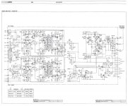
revox b285 receiver. It has a jfet differential pair with bjt cascode but i don't understand the circuit above or the vas section; also there is an unusual use of an ic dual opamp LF353 in the global feedback circuit. would anyone like to help descibe the topologies starting with the IPS?
there maybe improvements to make to the circuits as well.
thd is listed as <.03% 20-20k
<.005% at 1khz 70 watts into 8ohms
dynamic headroom 2.5db 8ohms
rise time 4us 8ohms -( not sure how it relates to slew rate?)
Its an interesting topology to analyze and learn about.
Attachments
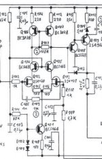
it looks like a current mirror but the way its connected looks strange booth collectors are connected to the cascode collectors it looks like a quad current mirror? how does it work with that 100k R? is it stabalizing the cascode?
It's a normal current mirror, but the 100k resistor is lowering the open loop gain (and increasing the bandwidth) of the input stage.
also there is an unusual use of an ic dual opamp LF353 in the global feedback circuit.
Hi,
Its probably a DC Servo to control the outputs DC offset.
rgds, sreten.
I'm trying to understand this unusual amplifier topology from the 1980's
revox b285 receiver. It has a jfet differential pair with bjt cascode but i don't understand the circuit above or the vas section; also there is an unusual use of an ic dual opamp LF353 in the global feedback circuit. would anyone like to help descibe the topologies starting with the IPS?
there maybe improvements to make to the circuits as well.
thd is listed as <.03% 20-20k
<.005% at 1khz 70 watts into 8ohms
dynamic headroom 2.5db 8ohms
rise time 4us 8ohms -( not sure how it relates to slew rate?)
Its an interesting topology to analyze and learn about.
Hi kissue,
The circuit above is a current mirror. It increases the gain of the input stage by raising the impedance of the load on the cascode transistor collectors. The current drawn in the inverting leg, with respect to the inputs, is mirrored in the non inverting leg of the current mirror. Of course the signal itself is inverted. The VAS is an ordinary one with a buffer transistor emitter coupled to the VAS transistor. This increases the gain and bandwidth of the VAS and isolates the input stage by increasing the impedance, again reducing the load on the IPS. Together this topology can increase the gain as much as 1000 times or more. The diode D403 is just a clamp to help prevent sticking if the amplifier is driven to clipping. The VAS is coupled in a folded cascode to the next stage. It's a two stage VAS.
Last edited:
; also there is an unusual use of an ic dual opamp LF353 in the global feedback circuit.
It appears to be an integrator for DC servo control.
Not to belittle an existing design but there are a couple of things I would have done differently. A Wilson mirror in the IPS would keep Vce and thus Pd of the mirror transistors equal. Or, I would have used a cascode arrangement, i e common base instead of a Zener for the buffer that feeds the folded cascode VAS. This way you could use a low Vce small signal device that has a large current gain, like a 2N5087 or a even a J-fet and eliminate a stage within the global loop. But then this is why I make my own amps.

Hi,
Its probably a DC Servo to control the outputs DC offset.
rgds, sreten.
Isn't it involved in the error correction? IC LF353 looks like its inverting the signal -some sort of high impedance inverting buffer that feeds back to the jfet differential pair? also the el capacitor appears to cause a filter effect. would like to know how it works.
wow there are a lot of smart people hear i'm digesting the info anld will get back to you- also i've been putting together a simulation using simplix simplistechnologies.com so i can post that here or somewhere later but i'm still trying to find models for the s2a.. 2sc.. and sk170 plus the diodes. wondering if the LSK170 would be a good substitute for modeling the jfet?
thanks for your interest and thoughtful replies
thanks for your interest and thoughtful replies
Last edited:
LSK170 is a direct replacement for the 2SK170
There is nothing that strange with the topology, except you do not often see the 100k resistor between the collectors of the current mirror, and a folded cascode VAS...
Revox is otherwise well known for hving some interesting twists in their designs, somewhat atypical by both european, US and japanese design standards of the time.
Last edited:
LSK170 is a direct replacement for the 2SK170
There is nothing that strange with the topology, except you do not often see the 100k resistor between the collectors of the current mirror, and a folded cascode VAS...
Revox is otherwise well known for hving some interesting twists in their designs, somewhat atypical by both european, US and japanese design standards of the time.
yes that 100k resistor connected across both collectors makes me wonder why not across one collector? isn't it a single ended output converter mirror?
what is a folded cascode vas? oh its a common base wonder why they use the term folded?
Last edited:
- Status
- This old topic is closed. If you want to reopen this topic, contact a moderator using the "Report Post" button.
- Home
- Amplifiers
- Solid State
- unusual amplifier topology jfet