I actually finally got it working!
it runs off exactly 6 volts from only 4 double A batteries no more no less
it has only one resistor and one capacitor.
there is zero background noise
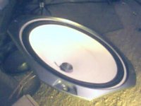
and it has enough power to drive a 12 inch subwoofer and gets some real bass!
it has zero distortion and I'm not even sure how long the batteries last but I'm sure they will last for a long time
there is only one teeny tiny drawback is that there is a small amount of dc flowing to the output speaker but it's not even noticeable with such a large 12 inch subwoofer
and the transistor doesn't even get warm
the capacitor is set on the base and the input from my computer but only to keep the DC from the batteries from flowing back to my computer
it works absolutely great and there is no buzzing sound when you touch the end of the input plug like the other amplifiers.
the sound quality is outstanding and it's fairly loud to the point when my mom tells me to turn it down lol.
i'm not exactly sure what value the resistor has but I was trying to get the perfect biasing so I have perfect output quality with no distortion and not too much flowing dc to the speaker output so I just tested a bunch of random resistors until I found one that makes it sound perfect and not have too much dc voltage flowing to the speaker output to make a difference..
I have placed it all in a cardboard box and taped it all together so it looks really nice.
the only physical things in my simple amplifier are 3 things.. one the transistor.. two. a single resistor. and three the capacitor to the input.
i could somehow draw a super simple diagram of how I have everything wired up if anyone wants to know exactly how I made it.
it runs off exactly 6 volts from only 4 double A batteries no more no less
it has only one resistor and one capacitor.
there is zero background noise
and it has enough power to drive a 12 inch subwoofer and gets some real bass!
it has zero distortion and I'm not even sure how long the batteries last but I'm sure they will last for a long time
there is only one teeny tiny drawback is that there is a small amount of dc flowing to the output speaker but it's not even noticeable with such a large 12 inch subwoofer
and the transistor doesn't even get warm
the capacitor is set on the base and the input from my computer but only to keep the DC from the batteries from flowing back to my computer
it works absolutely great and there is no buzzing sound when you touch the end of the input plug like the other amplifiers.
the sound quality is outstanding and it's fairly loud to the point when my mom tells me to turn it down lol.
i'm not exactly sure what value the resistor has but I was trying to get the perfect biasing so I have perfect output quality with no distortion and not too much flowing dc to the speaker output so I just tested a bunch of random resistors until I found one that makes it sound perfect and not have too much dc voltage flowing to the speaker output to make a difference..
I have placed it all in a cardboard box and taped it all together so it looks really nice.
the only physical things in my simple amplifier are 3 things.. one the transistor.. two. a single resistor. and three the capacitor to the input.
i could somehow draw a super simple diagram of how I have everything wired up if anyone wants to know exactly how I made it.
while i do understand your statisfaction, i still have to remaind you that this is chipamps section.
transistor based amps do not belong here.
and as a side note, that single transistor amp is surely a design that can use a whole lot of upgrades.
at best it would get you prehaps a watt.
maybe -since you are intrested in electronics- ask around for books on the subject, it is great to expermient with stuff but.. surely a solid basic knowledge would lead to roughly lightyears better results.
Your achivement is a great start never the less, maybe you should make some pictures of it, draw what you conected and how, i'm sure some of the responses will suggest nice additions to the amplifier.
as an example, i can give you one right away. A larger value capacitor connected in series with the speaker will block all DC from the speaker.
Probably You should do some research on simple transistor circuits.
Not that realy hard or costly to build a single transistor unit with voltage gain, and a nother stage with current gain for some real power. (like 5 watt or so would most probably be a big difference).
my problem is I only have 6 volts going one direction..... it needs to have another 6 volts going the other way too to have the full sinewave
and I tried that with the capacitor on the output to the speaker but when I try that all my sound goes away and I get no power at all going to my speaker. it fixes the DC problem but then I get extremely quiet sound since it's still only pushing the speaker one way..
by the way i'm already using a two in one darlington transistor so gain is not an issue
and I don't know how to find the transistor based amp section wherever that is can someone help me on that i'm still new here.
Last edited:
while i do understand your statisfaction, i still have to remaind you that this is chipamps section..........
He's excited to have a working project
OK, so this in now in the solid state forum... so how about posting a circuit so we can all see this beastie
..............I have placed it all in a cardboard box and taped it all together so it looks really nice.
the only physical things in my simple amplifier are 3 things.. one the transistor.. two. a single resistor. and three the capacitor to the input.
i could somehow draw a super simple diagram of how I have everything wired up if anyone wants to know exactly how I made it.
how about a couple of pictures
If your not sure how to attach anything to a post just ask.
witch is a fantastic thing.
i hope to see the schematic too, surely that amp can get better
bit on the technical stuff::
single supply does not mean the amplifier moves the speaker cone to one direction only.
The loss of power when connecting a capacitor can be for the following:
not connected series with the speaker, and/or the capacitor value is too low.
The transistor is a darlington (or that's what someone told me and when I looked at the data sheets of it.
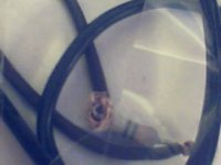
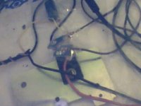
sorry my wiring is so messy i'm no good with a solder gun so i just use a lot of wires instead!
I'll draw a really quick diagram of how I have it set up and then i'll upload it soon.
i know something is totally out of place like the resistor or the power supply or possibly both including the speaker.. but it works mostly and sounds really loud and clear except for the DC flowing to the speaker
but I want to make it more beefier more bass and without the DC flowing to the speaker. (that's the difficult part)
Attachments
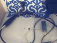
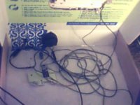
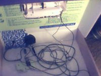

Thanks for the pictures
It reminds me of my first projects... a headphone amp I made using a single AD149 germanium power transistor. Mine lived a small plastic picnic sandwich box. Trouble is it leads to bigger things
Nothing beats hearing sound from something you first make.
Its a bit hard to make out from the pictures but from your description I think I can visualise the circuit.
To get rid of the DC in the speaker means adding more parts and reducing the efficiency but it is the way forward to a better design.
i think i can describe it better than i could draw a diagram so here goes..
the positive input wire goes to the base or pin 1 (lets lable the transistors leads pin 1 2 and 3)
and there is a resistor between pins 1 and 2
pin 2 goes to the positive wire of the power supply
the negative wire of the power supply goes to the positive speaker wire
and the negative wire of the speaker wire goes to the negative of the input. and the negative of the input goes to pin 3 of the transistor.
and there is a capacitor between the positive of the input and pin 1 of the transistor.
a little complicated but it works perfectly fine at only 6 volts four double A batteries.
trust me it won't work with any more or any less or it does weird things
(super heats the transistor or massive distortion if i take away one battery or add one more battery)
it works fine except for the amount of DC flowing to the speaker constantly wasting a bit of power
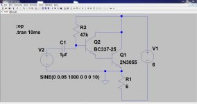
Hmmm... Nelson Pass had better watch out
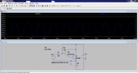
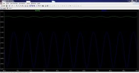
So this is what I think you have come up with. The two transistors here make a single "Darlington". The 6 ohm resistor is the speaker and the 47K is chosen to bias the transistor optimally.
It works and the distortion is even harmonic. The two traces show the input voltage and the output across the speaker. Plenty of voltage gain Connecting the input ground to the emitter rather than the battery negative changes the amp from an emitter follower (look it up) to a common emitter configuration.
Increase the supply and the power consumption rises dramatically as you have found. Decrease and you get distortion. You would have to alter the value of the 47K for each and every change in supply voltage with a circuit like this.
The biggest problem is the DC current in the speaker coil.
So this is what I think you have come up with. The two transistors here make a single "Darlington". The 6 ohm resistor is the speaker and the 47K is chosen to bias the transistor optimally.
It works and the distortion is even harmonic. The two traces show the input voltage and the output across the speaker. Plenty of voltage gain
Connecting the input ground to the emitter rather than the battery negative changes the amp from an emitter follower (look it up) to a common emitter configuration.Increase the supply and the power consumption rises dramatically as you have found. Decrease and you get distortion. You would have to alter the value of the 47K for each and every change in supply voltage with a circuit like this.
The biggest problem is the DC current in the speaker coil.
Attachments
actually my speaker is 4 ohms o.o
and my ears are super sensitive to distortion so I always make sure to keep the volume on my computer set just right so it doesn't have any distortion or it really messes up the sound quality. and i'm not exactly for sure know what resistor i have... it could be anything because since I took it off of a old TV motherboard i was trying a bunch of resistors until i found one that worked good enough so it could be anything..
and my ears are super sensitive to distortion so I always make sure to keep the volume on my computer set just right so it doesn't have any distortion or it really messes up the sound quality. and i'm not exactly for sure know what resistor i have... it could be anything because since I took it off of a old TV motherboard i was trying a bunch of resistors until i found one that worked good enough so it could be anything..
Last edited:
sorry it won't let me edit my post but I wanted to add that i think my batteries may be finally dying so i might have to go buy some new ones soon... (a little more distortion than usual today)
also I would have to hugely change the resistor if i wanted to have more power... i would need to change it enough so my amp has almost no power flowing through it because the more power i need.. i need a transistor that's even more ohms than before.. if i wanted to upgrade to a 12 volt power supply i would basically need to change it to almost 300,000 or something like that because if i add one more double a battery it makes the voltage in my amplifier go shooting through the roof..
by the way I don't use anything close to a 0.1uF or a 1.0uF
I use a 2200uF capacitor for the input for much more bass.. enough bass to move a 175 watt subwoofer! that's my good DUAL subwoofer i bought from walmart and not the paper speaker in the pictures i showed earlier.. i should make a video showing my home made amplifier powering the big subwoofer : D
and sure.. at certain frequencies of bass it distorts more than other frequencies.. though there is almost no treble or high frequency distortion which i think is pretty good
by the way there is no static or background noise whatsoever in this amplifier i made.. and no buzzing sound when i touch the end of the input plug like the other amplifiers make.
Last edited:
If you have around 3 volts (with new batteries) across the speaker and the speaker measures (say) 4ohm then the current flowing is I=V/R which is 0.75 amp. Lets say the capacity of a new alkaline cell is what, 2Ah, (it's in the right ballpark) so that gives a life of 2/0.75 which is around 2.5 hours.
The resistor sets the operating point. Ideally the resistor should be set to give around half the supply voltage across the speaker so that the signal can swing equally in each direction. Its value depends totally on the transistor characteristics... not good design... but to do it differently means you reading up a lot more on how transistors and basic circuits work.
You have a working design. Now you need to really understand how it actually works and why it behaves as it does
you should use the 2200uF cap for the output...
That takes it to a much more complex design
I agree the amp as it stands isn't practical but its a good starting point to learn.Look at how the amp achieves its voltage gain and also achieves a good voltage swing across the speaker.
omg I changed the resistor to a slightly smaller one and I changed my power supply to a 5 volt usb at only 700mA and now it's even more powerful than with the batteries and now my 12 inch subwoofer is getting what looks like.... at least 10-20 watts!! it's flexing like crazy now almost a fourth of an inch woofer movement! and there is less distortion than before! but the transistor gets a bit warm but it's not too warm since i changed the resistor to allow less DC to flow. it's about as warm as with the double a batteries but much more powerful
I do love to play with such kind of circuits too
Please teach me how to connect the wire...
- Status
- This old topic is closed. If you want to reopen this topic, contact a moderator using the "Report Post" button.
- Home
- Amplifiers
- Solid State
- I finally made a good working transistor amplifier