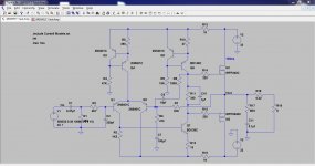
I don't have much experience with Audio amplifier design. I found one 25W MOSFET audio amplifier circuit. 25 Watt MosFet Audio Amplifier - RED - Page2
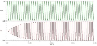
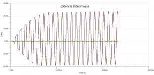
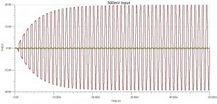
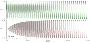
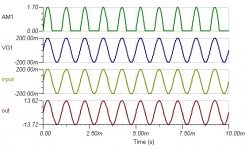
I like to start this design with simulation. My TINA simulation get clipping at output.
The circuit is proven & working but i don't know what is wrong with the simulation...
Facts and Figures - RED
Regards
Udhay
I like to start this design with simulation. My TINA simulation get clipping at output.
The circuit is proven & working but i don't know what is wrong with the simulation...
Facts and Figures - RED
Regards
Udhay
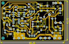
Attachments
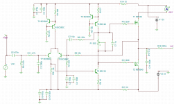
The gain of 70 is fine and the amp and its compensation and so on will have been designed around that figure. Although you could alter the value of R6 (increasing lowers the gain) I wouldn't do so in practice. It just means the amp has a high input sensitivity and as it says, no need for a preamp.
Can i use this for 5.1 Surround? Can i connect it into my DVD player or PC sound card? (Sorry i don't know the p-p signal Output voltage) without clip?...
Yes you can. The high sensitivity should work with most source components.
Just remember what I said about the bias stability though
")
Sorry, at 50% setting of the pot, the Iq of the output stage is only 75uA!
Setting the pot at 42% gives an Iq of 150mA, but as others have said, the quiescent varies wildly with temperature. This is to be expected when using VMOS FETs with no Source resistors. A proper temperature compensated bias is needed at least.
Setting the pot at 42% gives an Iq of 150mA, but as others have said, the quiescent varies wildly with temperature. This is to be expected when using VMOS FETs with no Source resistors. A proper temperature compensated bias is needed at least.
- Status
- This old topic is closed. If you want to reopen this topic, contact a moderator using the "Report Post" button.
- Home
- Amplifiers
- Solid State
- Need help to simulate my MOSFET Amplifier using TINA