Hi guys,
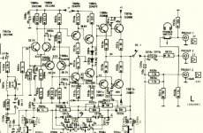
I'm looking at a transistor preamp service manual on which all the resistors in the signal parts of the circuit are 0.25W rated. However, a few are marked as 'Safe 0.25W'. See pic - an example are the 39 ohm ones near the output relay.
Can someone advise what makes these different from standard resistors?
Thanks
Stuey
Attachments
Overload safe.
If the output transistors fail as short circuit, as they usually do, then the 39R resistors will be overloaded. A "safe" resistor is tested to fail as open circuit when overloaded and without any flames or nasties. Other resistors may not need this safety because their value or circuit position is such that even a short circuit failure elsewhere will not overload them.
Best wishes
David
Thanks David. I guess that's what I'd surmised anyway, but I've never seen these listed for sale anywhere. What are they marketed as - do you know? I've had a quick look round, but can't see any. Are they just those claimed to be flame-proof, or is there more to it re. failing open?
Last edited:
Safety or fusible resistors are common in the service industry. They are designed to fail in a safe and predictable and repeatable way without letting off noxious fumes or smoke and also the consequential damage of charred PCB's and so on.
Heres a small selection if the link works,
CPC - Over 100, 000 products from one of the worlds leading distributors of electronic and related products. | CPC
Heres a small selection if the link works,
CPC - Over 100, 000 products from one of the worlds leading distributors of electronic and related products. | CPC
Good thread for info.
Worth adding that in analog TV days, with a lot of power dissipation in the circuits driving the CRT, certain resistors were mounted "upside-down" such that if they became extremely hot and melted their solder they would drop out and fall to the cabinet base!
Worth adding that in analog TV days, with a lot of power dissipation in the circuits driving the CRT, certain resistors were mounted "upside-down" such that if they became extremely hot and melted their solder they would drop out and fall to the cabinet base!
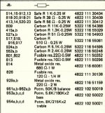
Guessing a little here but the fusible types I looked up were wire wound and, as per your parts list, this means only small resistance values will be feasible with small components.
Higher values, perhaps > 25R, will be different in construction - possibly just regular film types with a thick silicone coating to prevent or inhibit flaming.
So, it may just mean that those particular fusible types are only available or necessary in a limited range - after all, wire wound parts tend to be expensive.
Last edited:
another common name for them is "flameproof"..... only problem with them is it's often to tell visibly if they've blown. there may be a small black spot on them near the middle, but that's usually about it. in many cases, they're physically small for their rated wattage, so a 1 watt is the size of a 1/4 or 1/2 watt. the ceramic coating aids in heat dissipation.
Last edited:
FWIW, I used to think that carbon film resistors would provide some protection by burning up fairly easily, then I worked on something where the carbon film resistors carbonized to a lower and fairly robust value, making the situation worse, rather than providing any protection at all. A metal film will often melt the solder before it fails. Thus, pay close attention to what the manufacturer says in their data sheet.
Thanks guys.
Looking at their physical construction, the Safe resistors look exactly like the other carbon films in the circuit (it's a late 70's pre) but are greyish in colour and shinier, around the size of a generic 0.5w metal film. I know those 39R's get warm because the board is discoloured under them (they are not raised off the board).
However, the 1k resistors to ground (which are also marked as Safe) to the left of those 39R's in the circuit above are much larger and are standing off the board 10mm so I assume these get hot. These are slightly crumbly looking but still in spec.
The fusibles look similar to a 1w or 2w carbon film, but with sharper edged end caps and matte paint.
I should say, I'm replacing some of the carbons in the circuit with metal films (and some of the electro caps with film caps/none) to see if it might make the amp slightly less veiled in the highs, hence the questions. I assume the resistors won't make much (if any) difference to the sound, so it's no big issue if those safe R's can't be changed out.
Cheers
Stu
Last edited:
...
I know those 39R's get warm because the board is discoloured under them (they are not raised off the board).
...
However, the 1k resistors to ground (which are also marked as Safe) to the left of those 39R's in the circuit above are much larger and are standing off the board 10mm so I assume these get hot.
I expected after I posted my simple reply that there wouldn't be much more to discuss but this is a bit less clear than I expected!
AFAIK there is no commonly accepted standard that specifies what is meant by the informal use of the term "safe" resistors.
Safe-ish resistors can be either "flame-proof" or "fusible". Flame-proof are what they say - not certified to open-circuit, just that they won't burn.
Fusible obviously fail open-circuit and I assume that means no flames as well.
Not clear exactly what your pre-amp manufacturer means.
What brand is it?
It seems odd that the 39R resistors run hot in a pre-amp.
The circuit actually looks like a little power amp, with paralleled output transistors. Is it intended for low impedance headphones or some such?
Best wishes
David
It's a Philips AH280 from their so called Laboratory Series. I think they were also called Black Tulip. I've removed all tone controls and filters and am just seeing what sort of sound I can get out of it. I was given it and when I looked at the interesting all discrete build and quality parts, I assumed it might have some potential.
Regarding your power amp comment, yes that what I thought too. It uses TO126 package output transistors in the preamp. The phono stage is also of similar topology, but using discrete TO92 devices. The power supply supplies 50v, with the amp sections seeing around 40v.
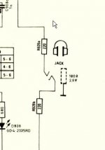
I'm not sure about headphones. I was going to use it to drive 32 ohm AKG's but I assume the unit is designed to handle down to only 180 ohm - see pic - what do you think? (Is that what the mfr meant by the dotted resistor?)
Regarding your power amp comment, yes that what I thought too. It uses TO126 package output transistors in the preamp. The phono stage is also of similar topology, but using discrete TO92 devices. The power supply supplies 50v, with the amp sections seeing around 40v.
I'm not sure about headphones. I was going to use it to drive 32 ohm AKG's but I assume the unit is designed to handle down to only 180 ohm - see pic - what do you think? (Is that what the mfr meant by the dotted resistor?)
Attachments
Last edited:
That's not a dotted resistor, it is the shell of the headphone jack. What they are telling you is that the pre-amplifier can deliver the specified voltage of 2.6V (rms?) into a 180 ohm load..
In its time head phone impedances ranged from < 8 ohms to > 600 ohms, so I would expect a 32 ohm headphone to work pretty well, but you'll have to try it to know.
In its time head phone impedances ranged from < 8 ohms to > 600 ohms, so I would expect a 32 ohm headphone to work pretty well, but you'll have to try it to know.
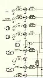
The specification probably just means that with an impedance of 180 Ohms, the output is 2.7 V.
On this Dutch website it says: "Uitgangsimpedantie: Luidsprekers & hoofdtelefoon 8-600 Ohm." Translated into English it says: "Output impedance: loudspeakers & headphones 8-600 Ohms."
Not sure why they would specify loudspeakers for a preamp, but this might have been lifted from documentation on preamp-power amp combo.
I don't think using 32 Ohm headphones should present any problems. (Stereo) jacks usually short signal and ground during insertion, and the circuit should withstand that. The 220 Ohm resistors in series with the audio signal to the headphones probably limit the current to a safe level in case of a short.
Thanks.
I believe this preamp was used to drive Philips motional feedback speakers. I'm not sure what this involved and whether they were driven direct, but if you have a look in the first post above you can see the third output which is +10dB which I think was for these speakers.
Other than that, I know nothing!")
Stu
I believe this preamp was used to drive Philips motional feedback speakers. I'm not sure what this involved and whether they were driven direct, but if you have a look in the first post above you can see the third output which is +10dB which I think was for these speakers.
Other than that, I know nothing!
Stu
Last edited:
- Status
- This old topic is closed. If you want to reopen this topic, contact a moderator using the "Report Post" button.
- Home
- Amplifiers
- Solid State
- What are 'safe' resistors?