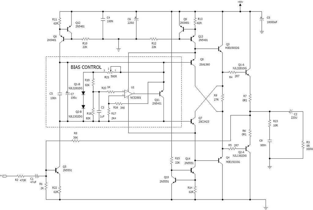
A while back I posted in the Bob Cordell Power Amp Book thread an op-amp based bias control schematic for a Diamond Buffer Triple (DBT) output stage utilizing the On-semi ThermalTrak output devices. Encouraged by the positive response I got around and put this design to bench test.
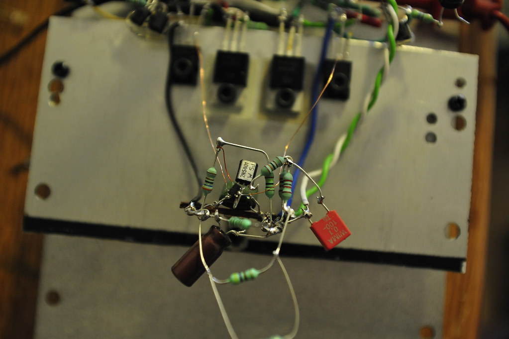
I rigged up a simple OTL amp based on two separate aluminum plates that serve as heatsinks, one big one for the TT transistors, the other one smaller for the pre-driver and driver transistors.
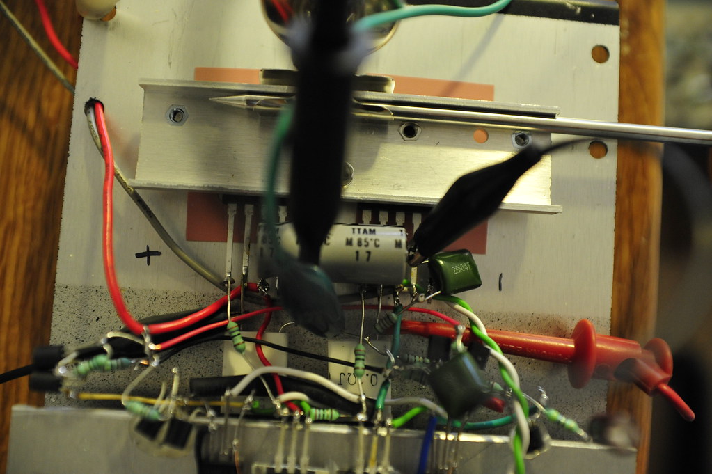
The op-amp is On-semi NCS2001. It's designed to operate off single cell Ni-MH battery swinging rail to rail, and is guaranteed to work on a 0.9V supply voltage. Can you find it in the picture?
In my original circuit I was assuming the bias voltage needed for a DBT output would be in the range of 1.1-1.4V, so I had the op-amp directly take supply on the bias voltage. The test result indicated that may not be a good idea. I found that the pre-driver transistors have a higher Vbe drop than do the driver transistors by 0.166V combined which jacks up the bias voltage by that much. At measured heatsink temperature of 70C I read a 0.975V bias voltage between the base of the pre-driver transistors, only 75 mV into the "green". So in the final circuit the op-amp gets power at the output of the pre-driver, comfortably at about 2.3V.
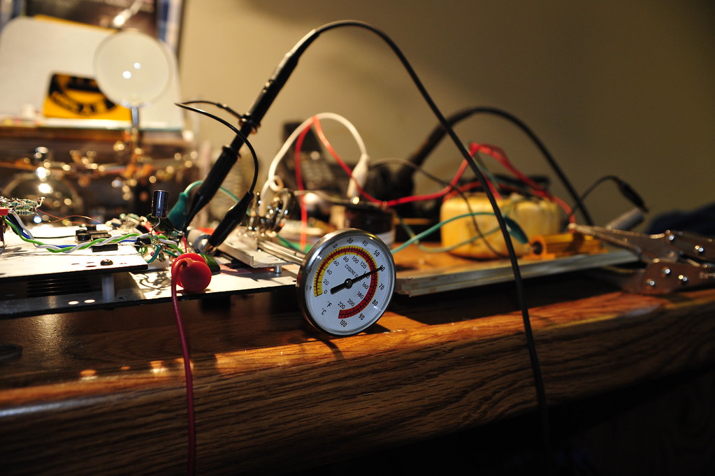
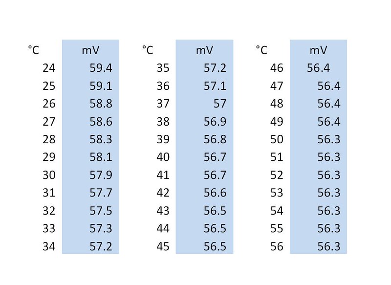
The bias voltage tracks temperature quite well. The power is turned on at 22C and I started taking readings at 24C. The voltage was taken between the emitter of the output transistors.
I'm now working on a power amp PCB design based on Fig. 3.14 of "The Book" featuring a DBT with max. 5 pairs of TT output transistors, TMC, solid state speaker relay, and I'll put this bias control in it.
I rigged up a simple OTL amp based on two separate aluminum plates that serve as heatsinks, one big one for the TT transistors, the other one smaller for the pre-driver and driver transistors.
The op-amp is On-semi NCS2001. It's designed to operate off single cell Ni-MH battery swinging rail to rail, and is guaranteed to work on a 0.9V supply voltage. Can you find it in the picture?
In my original circuit I was assuming the bias voltage needed for a DBT output would be in the range of 1.1-1.4V, so I had the op-amp directly take supply on the bias voltage. The test result indicated that may not be a good idea. I found that the pre-driver transistors have a higher Vbe drop than do the driver transistors by 0.166V combined which jacks up the bias voltage by that much. At measured heatsink temperature of 70C I read a 0.975V bias voltage between the base of the pre-driver transistors, only 75 mV into the "green". So in the final circuit the op-amp gets power at the output of the pre-driver, comfortably at about 2.3V.
The bias voltage tracks temperature quite well. The power is turned on at 22C and I started taking readings at 24C. The voltage was taken between the emitter of the output transistors.
I'm now working on a power amp PCB design based on Fig. 3.14 of "The Book" featuring a DBT with max. 5 pairs of TT output transistors, TMC, solid state speaker relay, and I'll put this bias control in it.
Exactly, Bonsai. Bob gave that recommendation as well. The added diodes eat slightly into the voltage swing but that usually is not a problem. We indeed have a vast pool of op-am we can choose from at 3V and up supply voltage level.
I have later put off the DBT OPS and went with "normal" 3EF, as I found the DBT possess some peaking in frequency response in simulation that was on the other hand not so much of a concern to me in a normal 3EF. I ran out of room in a compact PCB layout as well, as a DBT has a lot more components.
I have later put off the DBT OPS and went with "normal" 3EF, as I found the DBT possess some peaking in frequency response in simulation that was on the other hand not so much of a concern to me in a normal 3EF. I ran out of room in a compact PCB layout as well, as a DBT has a lot more components.
This aspreader is a nice way for mine circlotron design, I have 6 volts there but also 40 mA current because it is on a different place on the reference resistors, pull resistance there give a nice regulation for idle current, with a CF it did track quite nicely even until 70 degree celsius.
I do not now if I may use your spreader, the only change what need to be done is the circlotron needs inverted regulation done by the spreader resistor, I get lower idle when resistance go up, here it is lower idle when resistance go down.
Maybe with a simple chance I can use it with quite much succes.
thanks
regards
- Status
- This old topic is closed. If you want to reopen this topic, contact a moderator using the "Report Post" button.
- Home
- Amplifiers
- Solid State
- Op amp based DBT bias control put to test