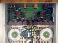
This is what I have come up with. Design is largely based on AW120, except original protection circuitry, voltage amp power supply
and a small twist on input stage biasing.
Would anyone care to comment on the pcb design, as it is getting toward completion? Left and right channel signal paths are mirrored except around the output transistors, where I have tried to keep respective trace lengths equal.
What would you do in a different way? Any other comments/ideas are welcomed.
Cheers.
Attachments
Last edited:
Welcome
Very nice project!
I would like to ask for help
Electrocompaniet AW-180 schematics I need
Thanks for your help
my email address
gargafater@freemail.hu
Very nice project!
I would like to ask for help
Electrocompaniet AW-180 schematics I need
Thanks for your help
my email address
gargafater@freemail.hu
That' d be the schematic.
Hello hollow_man
I saw the schematic of the amplifier and i was wondering how the feedback network from the "OutR" works. It seems it goes to a 8K2 resistor, but i would expect a second resistor from there connecting to ground. As it is now it seems like being an amplifier with 0 dB gain.
Hi Powjemini,
this design is along the typical EC lines, whereby the first section of the amp operates open loop as a transimpedance amplifier with a very high output impedance. However, it 'sees' the 8K2 output section feedback resistor as its load, which establishes a given voltage gain. The output section indeed operates with 100% negative feedback, so its voltage gain is unity.
Hence you could say that the voltage gain is determined solely by the 8K2 feeback resistor (within limits).")
Regards,
hollow
this design is along the typical EC lines, whereby the first section of the amp operates open loop as a transimpedance amplifier with a very high output impedance. However, it 'sees' the 8K2 output section feedback resistor as its load, which establishes a given voltage gain. The output section indeed operates with 100% negative feedback, so its voltage gain is unity.
Hence you could say that the voltage gain is determined solely by the 8K2 feeback resistor (within limits).
Regards,
hollow
AW120 diy clone
Hi jorgovanko,
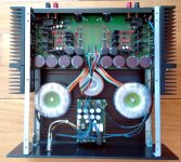
just a hastingly taken picture of the AW120 clone machine as it stands. As a matter of fact, I have a new chassis specifically built for the purpose by a friend that is more spacious and offers better cooling, so I will be transplanting soon.
As I said I have given up on the higher power clone due to costs and time constraints.
Cheers.
Hi jorgovanko,
just a hastingly taken picture of the AW120 clone machine as it stands. As a matter of fact, I have a new chassis specifically built for the purpose by a friend that is more spacious and offers better cooling, so I will be transplanting soon.
As I said I have given up on the higher power clone due to costs and time constraints.
Cheers.
Attachments
Thanks for the kind words jorgovanko.
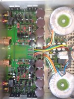
The original pcb is deeper and has the trafo cutout in the middle, i.e. it is geared toward a shared trafo between the two channels (with isolated secondaries per channel). So I though I might as well go for separate trafos per channel, hence the newer pcb.
It turns out the idea of paralleled relays at the output is a bad one, so I have hacked the pcb to include a single higher-current one per channel.
There is also an extra pcb taking care of the trafo soft-start, bypassable mains dc blocking and soft power on/off.
The voltage gain stages have their separate power transformer.
hollow
Attachments
Last edited:
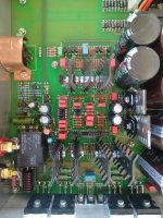
I worked over this weekend long times to make minor corrections to the schematic and pcb. The changes have mostly to do with the protection circuit which is my design. The two channels are now completely isolated using an optocoupler. Protection relays are changed to Omron G8P-1A4P-48VDC, now discontinued but still available and good enough to withstand an output transistor short without contact welding. Also the XLR footprint is changed to a better, shielded Neutrik part, type NC3MBH. Lastly I added some 23Amp capable Molex connectors for the power transformer board to wire connection and made some component shifting to allow for improved heat sinking.
Cheers,
hollow
Cheers,
hollow
Attachments
I think this amp is a bit too complicated for my taste, but I'm sure it sounds very refined, just like premium blended scotch whisky. ( Chivas Regal?)
A fairly complex design should give the designers a large set of parameters to tweak or "voice".
Nelson Pass has a harder work when he want's to tune the sound of the First Watt F5, for example, since there are so few things to alter.
Some told me that Electrocompaniet spent a lot of time "voicing" the amp - sometimes to a degree where they found it hard know when to stop, when the drawing was finished, and they found themselves walking in circles a bit.
And, Hollow_man, you talked about the 8k2 resistor that set the gain. Yes it does so, but the output stage isn't a unity gain stage. The "input" part of the 8k2 resistor is actually a virtual ground.
Don't you agree?
Hi Svitjod,
I am sure EC listen to their amplifiers just like any other serious audio firm, even though they have got a strong engineering rationale behind their designs.
A major part of this is their open loop input transconductance amplifier that sees this 8k2 resistance as its load.
I am sure EC listen to their amplifiers just like any other serious audio firm, even though they have got a strong engineering rationale behind their designs.
A major part of this is their open loop input transconductance amplifier that sees this 8k2 resistance as its load.
- Status
- This old topic is closed. If you want to reopen this topic, contact a moderator using the "Report Post" button.
- Home
- Amplifiers
- Solid State
- New Electrocompaniet AW120 clone