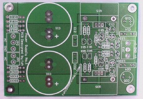
A wide-range (¡À5V-¡À60V)regulator design for use in headphone amplifier and its tiny size is also suitable for replace the power supply in CD player... 
A 108mm*77mm Double side PCB
My work:
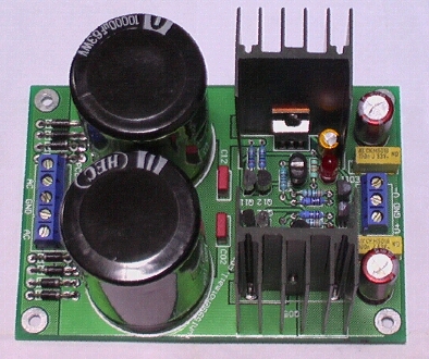
Look!The transistors of differential amplifier is thermal couping(Q03-Q04,Q13-Q14).
A 108mm*77mm Double side PCB
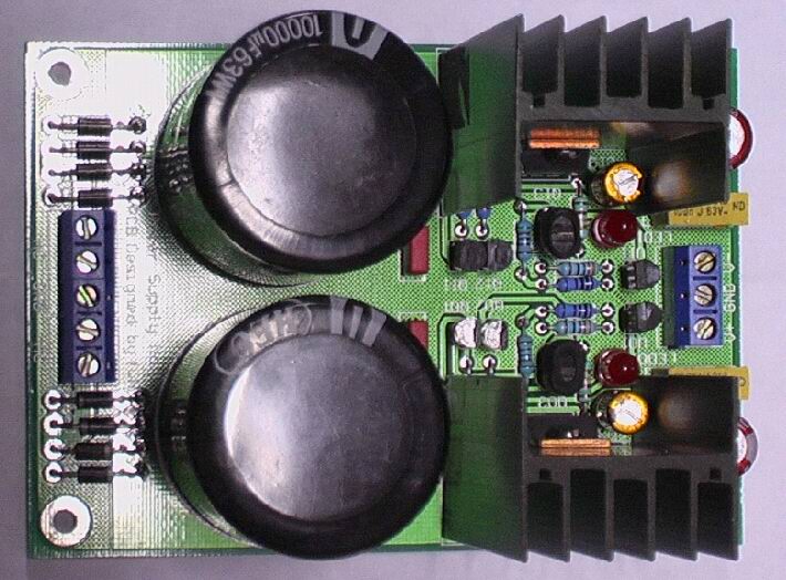
My work:
Look!The transistors of differential amplifier is thermal couping(Q03-Q04,Q13-Q14).
Thank you.peranders said:No comments, not even from Fred :schratch:
I'll see that you have made some cross posting but it's still a neat CAD job. What shall you use it for?
Beacuse my English is very poor,I can't talk it very cleanly,Sorry.
I used it for modify my CD player and Head_AMP supply,I will use it for Pre_AMP.
Some cross posting for the Track (Electric to GND) is very strong.
I'm sorry my English is no good.

Answer some question here
Thank friends E-Mail to me,I answer some question here:
1,How to account Output Voltage:
VCC=2.5V*(1+R06/R05)
VEE=-2.5V*(1+R16/R15)
so you can change R06 and R16 obtain the output Voltage you need.
2,About R02 and R12:
R02/R12 limited the current passed LED01/LED11 is 2mA to 3mA.So R02=(Vin-1.65V)/2.5mA,the Vin is Voltage on C01,LED is red.as same as R12.
3,Diameter of C01/C11 in PCB:
the diameter is 35mm,and distance of pin to pin is 10mm and 17.5mm,so I can used 10000uF/63V in my work.
I'm sorry for my English,I wish you can understand,thanks.
Discrete Regulator
Hi fwh1599,
I would use a current mirror to load the differential pair like in this picture:
Taken from http://www.metaxas.com/pages/masnewfiles/index.html
Click on do it yourself, then on CP-3 preamplifier.")
Hi fwh1599,
I would use a current mirror to load the differential pair like in this picture:
Taken from http://www.metaxas.com/pages/masnewfiles/index.html
Click on do it yourself, then on CP-3 preamplifier.
Attachments
Elso Kwak:
Thanks for your information.
Yes,it's a discrete regulator.
Although use a potentiometer to replace R05/R15,it will be alterable.
But I think potentiometer is precarious.After a half of year,Its value will change,and regulator output for audio is 5V(for digi) ,15V(for op ,etc), 35V,40V or 50V(for Amp) ,etc.During using,we needn't adjust it.
- Status
- This old topic is closed. If you want to reopen this topic, contact a moderator using the "Report Post" button.
- Home
- Amplifiers
- Solid State
- This is my new work_A Series Linear Regulator