Here is the guide again ")
Build guide
--------------------------------------------------------------------------------
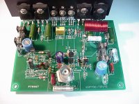
C6,R20,R27,R30,R31,R33 are mounted on the bottom of the PCB.
R33 is a ground lift resistor that could be around 7.5 Ohms, I would first use 0 ohms and if hum was encountered would then go fancy with the ground lift.
Heres you could do it.
1. Test all your components for defects including PCB
2. Stuff PCB starting with small components working your way to large components i.e. output transistors
3. Examine assembled unit for any solder issues or bent pins shorting others
4. Attach assembled unit to PCB isolating the transistors from heat sink.(Test this)
5. Ensure bias trim pot is set for maximum resistance
6. Attach bulbs on positive and negative rails
7. Do a jig then power up, if bulbs light up, wash rinse repeat, you may have done this in poor light
8. If all goes well, set bias, attach scopes and torture amplifier, if it holds up
9. Plug in your speakers (some use speaker protection)
10. Plug in the "I like to move it move from Madagascar" CD (I now have a newer song to be revealed later)
11. MOVE IT !!!!!!!!!!
12. WE LIKE TO............
Build guide
--------------------------------------------------------------------------------
C6,R20,R27,R30,R31,R33 are mounted on the bottom of the PCB.
R33 is a ground lift resistor that could be around 7.5 Ohms, I would first use 0 ohms and if hum was encountered would then go fancy with the ground lift.
Heres you could do it.
1. Test all your components for defects including PCB
2. Stuff PCB starting with small components working your way to large components i.e. output transistors
3. Examine assembled unit for any solder issues or bent pins shorting others
4. Attach assembled unit to PCB isolating the transistors from heat sink.(Test this)
5. Ensure bias trim pot is set for maximum resistance
6. Attach bulbs on positive and negative rails
7. Do a jig then power up, if bulbs light up, wash rinse repeat, you may have done this in poor light
8. If all goes well, set bias, attach scopes and torture amplifier, if it holds up
9. Plug in your speakers (some use speaker protection)
10. Plug in the "I like to move it move from Madagascar" CD (I now have a newer song to be revealed later)
11. MOVE IT !!!!!!!!!!
12. WE LIKE TO............
Well Harrison......I'm impressed
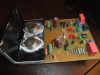
I finally had time to complete the boards today, have mocked up the parts on a peice of board and ran it on my system for a few hours tonight! wow the bass is powerful, and clean!
http://s1155.photobucket.com/albums/p551/Dagwood72/1DIFFQC/
I finally had time to complete the boards today, have mocked up the parts on a peice of board and ran it on my system for a few hours tonight! wow the bass is powerful, and clean!
http://s1155.photobucket.com/albums/p551/Dagwood72/1DIFFQC/
Last edited:
Harrison
Why not put the right valu for the bias into your guide list (pkt. 8)??
I have almost finished my 1DFFQC. I set the bias on one channel from very simpel power 2x35 v DC yesterday. No serious listenings, only from a crappy loadspeaker from the garbish. Had to put a 510 ohm resistor to R 14. I did it from the component side(lazyness) and not the soldering side. With 1 Kohm I did not get the bias as low as 21 mV.
In the finished version I will use a stabilized power 2x48 V DC, the same as I used in my SYNEF. This outranged my Golmund Mimesis 6 clone(in the high).
Will the 1DIFFQC also outrange my Goldmund Mimesis 9 clone ( I run active)in the middle?
I will be back later , and hopefully with an answer to that question and more pictures.
I have got a fine and big chassis from my friend Roar Malmin. Nice guy.He is always there to help.
In the final version the SMEF and the 1DIFFQC will be housed in the same chassis with four stabilized power(ok. I know that Harrison have adwised me to use unregulated).
Eivind Stillingen
Well Harrison......I'm impressed
I finally had time to complete the boards today, have mocked up the parts on a peice of board and ran it on my system for a few hours tonight! wow the bass is powerful, and clean!
1DIFFQC pictures by Dagwood72 - Photobucket
Very nice.
 . Thanks for making a difference, by taking a risk and joining us. Thanks for making your mark in improving the state of the art. Do keep us up to date. Nice tubes you got there . We wanna hear more
 Will the 1DIFFQC also outrange my Goldmund Mimesis 9 clone ( I run active)in the middle?
I will be back later , and hopefully with an answer to that question and more pictures.
Eivind Stillingen
Thank you for your zeal, looking forward to your review
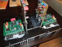
All parts installed and amp works great.
Very nice glad you like it
. Thanks again for joining us.Hello Everybody,, A quick update 1-on the first channel that I builded I used TIP142 transistors I enjoyed the sound very much my supply was at 37-+ volts. Then I try Changing my outputs and I used another suppy 45-+ The outputs are now MJH6284
Now this amp has come alive The bass takes you to the center of the earth and the highs put you on cloud 9. You,ll end up listening to your whole collection of music again.
Evette,
Do you've any MJH6284 trannies left for me?
Hi Harrison
Question....I've made up a speaker protection circuit found in Silicon Chip magazine http://i1155.photobucket.com/albums/p551/Dagwood72/1DIFFQC/SpeakerProtectionCircuit2.jpg
Do you think your design will be fine running with the speakers disconnected if I were to use the "over temp" connection as a mute switch?
Cheers
Dagwood
Hi Harrison
Question....I've made up a speaker protection circuit found in Silicon Chip magazine http://i1155.photobucket.com/albums/p551/Dagwood72/1DIFFQC/SpeakerProtectionCircuit2.jpg
Do you think your design will be fine running with the speakers disconnected if I were to use the "over temp" connection as a mute switch?
Cheers
Dagwood
Thanks Dagwood. Although I haven't looked at the circuit, normally transistor amplifiers have no problem with being unloaded
Harrison
Why not put the right valu for the bias into your guide list (pkt. 8)??
I have almost finished my 1DFFQC. I set the bias on one channel from very simpel power 2x35 v DC yesterday. No serious listenings, only from a crappy loadspeaker from the garbish. Had to put a 510 ohm resistor to R 14. I did it from the component side(lazyness) and not the soldering side. With 1 Kohm I did not get the bias as low as 21 mV.
In the finished version I will use a stabilized power 2x48 V DC, the same as I used in my SYNEF. This outranged my Golmund Mimesis 6 clone(in the high).
Will the 1DIFFQC also outrange my Goldmund Mimesis 9 clone ( I run active)in the middle?
I will be back later , and hopefully with an answer to that question and more pictures.
I have got a fine and big chassis from my friend Roar Malmin. Nice guy.He is always there to help.
In the final version the SMEF and the 1DIFFQC will be housed in the same chassis with four stabilized power(ok. I know that Harrison have adwised me to use unregulated).
Eivind Stillingen
Hi Liliya, hope all is well
Last edited:
Hi Harrison
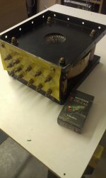
My transformer has arrived from Trade Me ( NZ E-bay ), it's a bit bigger than I thought it would be
1300Va
Output 1, 31volts @ 17.5 A
Output 2, 31volts @ 17.5 A
Output 3, 31volts @ 6 A
13.8 Kg's
No loss of power here....but will need a soft start for this puppy!
My transformer has arrived from Trade Me ( NZ E-bay ), it's a bit bigger than I thought it would be
1300Va
Output 1, 31volts @ 17.5 A
Output 2, 31volts @ 17.5 A
Output 3, 31volts @ 6 A
13.8 Kg's
No loss of power here
....but will need a soft start for this puppy!Attachments
Last edited:
Hi Harrison
My transformer has arrived from Trade Me ( NZ E-bay ), it's a bit bigger than I thought it would be
1300Va
Output 1, 31volts @ 17.5 A
Output 2, 31volts @ 17.5 A
Output 3, 31volts @ 6 A
13.8 Kg's
No loss of power here
What is the no load input VA? Maybe 500 VA or more.
- Home
- Amplifiers
- Solid State
- 1DIFFQC amplifier