Hi .
i have aquired these amplifier boards . they where removed from a mixing desk that had been partly destroyed by vandles. In the schematic at the top left there is a control circuit. i would like to remove or defeat this part of the circuit. Any help or advice would be very welcome .
mark
i have aquired these amplifier boards . they where removed from a mixing desk that had been partly destroyed by vandles. In the schematic at the top left there is a control circuit. i would like to remove or defeat this part of the circuit. Any help or advice would be very welcome .
mark
Attachments
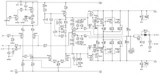
LTP, everybody knows what an LTP is except me and possibly madtecchy. Is the LTP the pair of input bipolar junction transistors like Tr4 and Tr5 in this schematic? They look like the input stage of an op amp. What is the second transistor for? Most of the BJT transistor schematics on solid state forum have the second one. None of my amps have them, the ST120 has a single input transistor and the Peavey's have op amps.
Last edited:
Thankyou andrew.. @ indiana i know what a long tail pair is and looks like on a schematic . The question was about the control circuit that is in series with the positive supply of the ltp..If i am not mistaken the st 120 is a single ended amplifier . Now to find out the correct current for the ltp to run nicley..
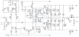
Thankyou djk. im assuming this type of circuit is used primarily in pa equipment as a reliabilty measure.. I notice the current limit circuit connects to the feed back loop and the +and - signal rails . does this type of circuit have a negative effect on sound quality.
mark
mark
"does this type of circuit have a negative effect on sound quality."
Not really, unless you activate it driving a loudspeaker. If properly designed, and the amplifier is used properly, you will not hear it.
Using the Leach amplifier as an example, if you drive a 2Ω load into hard clipping the limiter will engage. This will make a loud 'frapping' type of sound.
Not really, unless you activate it driving a loudspeaker. If properly designed, and the amplifier is used properly, you will not hear it.
Using the Leach amplifier as an example, if you drive a 2Ω load into hard clipping the limiter will engage. This will make a loud 'frapping' type of sound.
Hi djk.
I have now managed to salvage the control /psu board for this amplifier and also the quite large toroid that powers it . everything looks to be fine on the boards . No bulging caps no burnt components or scorch marks. i have tested the output stage and all transistors tested ok on a DMM. I will fire it up later on a dim bulb tester . One thing i have noticed is the psu puts out approx 63 Vdc and the four smoothing caps are rated at 63Vdc. it has run like this for the last ten years so i guess it will be ok to leave them for testing . If the amp is ok i will replace them with 100 Vdc types when i do the re cap
I have now managed to salvage the control /psu board for this amplifier and also the quite large toroid that powers it . everything looks to be fine on the boards . No bulging caps no burnt components or scorch marks. i have tested the output stage and all transistors tested ok on a DMM. I will fire it up later on a dim bulb tester . One thing i have noticed is the psu puts out approx 63 Vdc and the four smoothing caps are rated at 63Vdc. it has run like this for the last ten years so i guess it will be ok to leave them for testing . If the amp is ok i will replace them with 100 Vdc types when i do the re cap
Potted centre
Unfortunatley the transformer has a potted centre so not possible to add out of phase or remove in phase windings. The main smoothing capacitors are original and the powered mixing desk was used for background music aswell as live gigs so has done many hours I will be recapping it just for good measure. The main reason i mentiond the caps only being 63VDCis i could not belive a large manufacturer would have fitted these also i am quite surprised they have lasted so long. they even quote 63Vdc caps in the original scematic. As for the price of 100Vdc caps im not too worried as the rest of this amplifier came free of charge.
Regards Mark
Hi AndrewReduce the voltage from the transformer by adding a few dozen primary turns.
Reduces the temperature of the transformer and possibly makes it mechanically quieter as well.
Unfortunatley the transformer has a potted centre so not possible to add out of phase or remove in phase windings. The main smoothing capacitors are original and the powered mixing desk was used for background music aswell as live gigs so has done many hours I will be recapping it just for good measure. The main reason i mentiond the caps only being 63VDCis i could not belive a large manufacturer would have fitted these also i am quite surprised they have lasted so long. they even quote 63Vdc caps in the original scematic. As for the price of 100Vdc caps im not too worried as the rest of this amplifier came free of charge.
Regards Mark
Last edited:
63V?
75V or 80V would be enough margin for me.
Might do 300W/4Ω for you, sounds like you have a nice project!
Hi djk.
The amplifier is rated by the maker as being 350 Rms into 4 Ohm's and 210 Rms into 8 Ohm's. it uses a higher voltage rail at 73 volt to power the front end and Vas. yes it is a bit of a project and has far too much power for my needs . oh yea i nearly forgot as this amplifier has a balanced input can i just take the inverting input to audio ground so i can drive it from a single ended source.
Best regards mark
If this is BJT output stage then that power confirms a 45Vac transformer.210 Rms into 8 Ohm's.
41Vac is very close to the absolute maximum that can be used with 63V capacitors.
I too have a high quality amplifier that uses a 35Vac transformer and 50Vdc capacitors. This practice is a scandal, no matter how good they claim the sound quality.
"The amplifier is rated by the maker as being 350 Rms into 4 Ohm's and 210 Rms into 8 Ohm's."
A 1Khz rating I'm sure (standard for PA), nothing wrong with that.
"can i just take the inverting input to audio ground so i can drive it from a single ended source. "
Yes.
" i could not belive a large manufacturer would have fitted these"
A large manufacturer (that will remain nameless) used to make a PA amplifier with 85V using a 75V cap. Another (very well respected name) hi-fi manufacturer used to run 52V on 50V caps.
When Peavey amplifiers with 52V rails and 55V caps would need replacement I would always use 63V. Same with the Bryston 3B.
I prefer to have 10% margin, and allow another 10% for high line voltage (76.23V for your 63V example, I could live with 75V or 80V).
Hi Andrew
Yes the amplifier uses BJT MJ 15003 and MJ 15004 two of each . Im not sure how this amplifier will sound . The unit is more like 15 years old and im shocked the caps have lasted this long . Also it only uses two 3300uF caps in parrallel per rail to feed two channels. They look real small too for this power level . Anyway time to stop wondering and time to fire it up . Fingers crossed
Regards Mark
Hi djk
Advice apreciated i will use 80 Vdc .Now for the 73 volt rail. It only uses 16Vdc caps for smoothing . The twist is they have smoothed the higher 73 volt rail against the lower 63 volt rail of same polarity and not to ground . from what i have learned form diy audio im really noe sure that is good sound quality practice to me it looks like thay have found a cheap way to screw the last watt out of this amp so it looks good on paper. Aparently it was supposed to be a very good unit in its day But then again it is a PA amplifier . .
Advice apreciated i will use 80 Vdc .Now for the 73 volt rail. It only uses 16Vdc caps for smoothing . The twist is they have smoothed the higher 73 volt rail against the lower 63 volt rail of same polarity and not to ground . from what i have learned form diy audio im really noe sure that is good sound quality practice to me it looks like thay have found a cheap way to screw the last watt out of this amp so it looks good on paper. Aparently it was supposed to be a very good unit in its day But then again it is a PA amplifier . .
- Status
- This old topic is closed. If you want to reopen this topic, contact a moderator using the "Report Post" button.
- Home
- Amplifiers
- Solid State
- power amp help please