Hi,
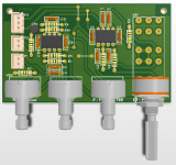
Here the very famous subwoofer filter circuit & also my PCB 3D component view.
I didn't check the circuit & quality. I hope it will work. After my testing i will post the PCB layout(single layer).... Meanwhile any commands about the circuit performance or any experience with this circuit.....
If any body interested in this Layout(Test it your self), Please give me a email..
I don't want to post the layout without test......
My contact embudhay@gmail.com
Regards
Udhay
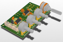
Attachments
It looks OK for what it is.
I did a variation that used an inverting input buffer as a three input summer. This allowed me to trim the .1 LFE input resistor for a different level than the 2.0 stereo input.
The level of the sub could be set for best sound on 2.0 (music), and then when the .1 LFE kicked in on a movie it could be adjusted to a higher level. Thus the switching was automatic.
- Status
- This old topic is closed. If you want to reopen this topic, contact a moderator using the "Report Post" button.