I just pulled out two different makes of faceplate XLR sockets...........This project is the first where I've used XLR jacks and hence do not have any prior working experience with them. My question is; I bought and used the plastic style that have 2 adjacent holes for mounting and securing to a plate. It appears that these screw holes are not threaded and therefore you would need to used self-tapping screws, or a nut. Is that the case? Also, it appears they are 2mm in size. Can someone confirm these two little facts about XLR jacks? ...........
Both easily take a 3.5mm diameter screw. But the head of a 3.5mm countersunk looks big and to my view rather ugly.
The 3mm countersunk looks nice.
Do you know how to convert from and back again between inches and millimetres?
2mm is only 78.74mil (thou in UK).
Last edited:
Hey Redjr,
I tapped my XLR's with a 4-40 tap and used the corresponding screws. Not hard,but takes a while because there are so many. Used black screws to match my rear panel. Thought about the self tapping but decided against them for fear of splitting the plastic.
I bought a small break to bend some aluminum for shielding the power supply. Turned out great. Last thing I want to do before I consider the project finished is to put something akin to Dynamat on the chassis for some vibration control. After that, it's on to the next project- either an Aikido pre amp, a PoddWatt integrated amp (already have most parts and pc board designed) or a Cavalli EHHA revA. Plan to end up with all 3 but have not decided which one to start with.
Looking forward to seeing pictures of your front and rear panels.
Jim
FyiI bought a small break to bend some aluminum for shielding the power supply
You may want to consider steel rather than aluminum, as a material for magnetic field shielding!!
For plastic, you need a thread forming type screw, but tapping the plastic works, as you have done. A course thread is better to use than a fine thread, 4-20 UNC vs 4-40 UNF
Good Luck
Rick
Last edited:
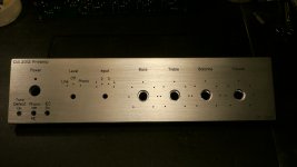
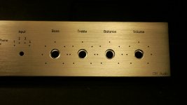
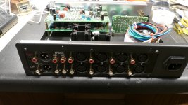
Here are a few pics of my panels. The front panel looks 'goldish', but it's really brushed silver. While the cutouts for the back panel connectors were near perfect, the way the back panel fits onto my case will present some challenges to get it all to fit right. Some metal work modifications will be required. The front turned out good too, but the cavity holes on the 4 large holes on the right turned out smaller than what they should have been. Maybe it was my mis-measuring and not allowing a wide enough cavity. I was planning on using the supplied 3/8" nut on the pots to secure it from the front since my panel is so thick (8mm). So now I'm trying to find some 3/8" knurl nuts that will fit down in the cavity and still allow me to tighten them up. My knobs are wide enough to cover the cavity holes so I was not to concerned with the nut being on the front. Oh the joys of doing it the DIY-way! ")
If I had to do all over again, I would opt for a bigger enclosure. This one will end up being too tight I'm afraid once all the modules are installed and wired up.
If I had to do all over again, I would opt for a bigger enclosure. This one will end up being too tight I'm afraid once all the modules are installed and wired up.
Attachments
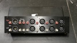
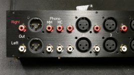
I intend to use shielded cables to/from the phono board. After making some measurements tonight on my 4 cavity holes, I discovered they were milled to the wrong diameter! Smaller by .33mm than my file specified. I've contacted FPE, so will see what they say.Looks great. The only thing I would do is replace the ribbon cable (if nowhere else do the phono inputs) with shielded pairs.
Update... My bad
A while ago I ordered a variety of spiffy brushed chrome knobs from vt4c.com. [BTW, this is a great website and has loads of stuff for the DIY'er.] I wanted the knobs so I would have a reference of the size perspective to the front panel I was laying out in FPE. After they arrived, I was so engrossed in seeing how they were looking on my mocked up front panel, I never thought to see if they actually fit the 4 main pots of the design. Well tonight I found out. They don't! Much to my dismay, I was sad to learn that it will be next to impossible making them fit without boring the center out by a mm or two. Which will be extra hard without a drill press. The shafts of the spec'ed pots are solid metal and are bigger than the holes in the knobs ordered from vt4c Studios. Urgh!
Now, call me naive, but I thought the shaft of most widely accepted pots and such have a standard diameter size. Sometimes they're groved, other ones have a a solid shaft made either of plastic or aluminum. SOme even have a flat side for proper orientation, etc. I used the standard expensive 1k Vishay pots as called out in the pre-amp design. So, is the reason they will not fit an issue between metric size holes and English standard pot shafts? What is the standard size pot shaft diameter? My bad for overlooking this in my design.
So what to do? I guess I'll now have to look for other knobs that will fit these pots, but after spending $100USD (I bought more for other projects too.) on some really nice looking solid aluminum knobs I'm bummed. Can anyone provide a link to a site that specializes in knobs.
A while ago I ordered a variety of spiffy brushed chrome knobs from vt4c.com. [BTW, this is a great website and has loads of stuff for the DIY'er.] I wanted the knobs so I would have a reference of the size perspective to the front panel I was laying out in FPE. After they arrived, I was so engrossed in seeing how they were looking on my mocked up front panel, I never thought to see if they actually fit the 4 main pots of the design. Well tonight I found out. They don't! Much to my dismay, I was sad to learn that it will be next to impossible making them fit without boring the center out by a mm or two. Which will be extra hard without a drill press.
The shafts of the spec'ed pots are solid metal and are bigger than the holes in the knobs ordered from vt4c Studios. Urgh!Now, call me naive, but I thought the shaft of most widely accepted pots and such have a standard diameter size. Sometimes they're groved, other ones have a a solid shaft made either of plastic or aluminum. SOme even have a flat side for proper orientation, etc. I used the standard expensive 1k Vishay pots as called out in the pre-amp design. So, is the reason they will not fit an issue between metric size holes and English standard pot shafts? What is the standard size pot shaft diameter? My bad for overlooking this in my design.
So what to do? I guess I'll now have to look for other knobs that will fit these pots, but after spending $100USD (I bought more for other projects too.) on some really nice looking solid aluminum knobs I'm bummed.
Can anyone provide a link to a site that specializes in knobs.BTW, FPE got back to me and without question sent me a UPS label for use. In the mean time, I ordered some different style 3/8" nuts that look like they will work in the smaller cavity hole. I'm waiting for them to arrive. Hopefully the'll work out and I won't have to send back my FP for re-work. Stay tuned.I intend to use shielded cables to/from the phono board. After making some measurements tonight on my 4 cavity holes, I discovered they were milled to the wrong diameter! Smaller by .33mm than my file specified. I've contacted FPE, so will see what they say.
A few more pics...
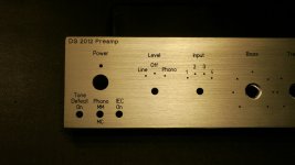
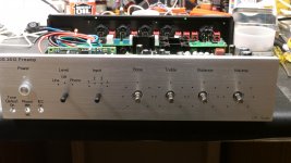
Here are few latest pictures. The front panel sans knobs that won't fit! I think I've narrowed down my final layout options as shown. Hopefully, the traffo won't be an issue with hum inside the case, but I may have to put a shield around it. It's getting closer...
Trouble with uploading pics. Will try later.
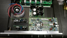
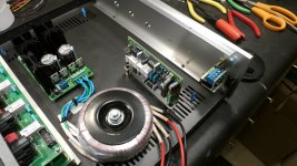
Here are some more pics.... I'm almost to the point where I can start anchoring down all the boards and start on the wiring process, but before I do that I will wire the traffo to the PSU and get a reading on the voltages to ensure there are no issues. Then it should just be a matter of finalizing the intra-connect lengths and plugging everything together.
Attachments
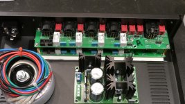
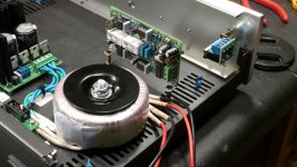
A few more construction photos of my progress. Got the mains, switch, traffo and PSU wired up today. Checked voltages and everything looked good. If you're wondering what the little blue tits are sticking up from the bottom.... I used some self-tapping screws to attach the rubber feet and then used some heat shrink tubing to cover the exposed screw. Not the most elegant solution, but it appears to work!
Attachments
Last edited:
You mean I didn't 'twist' good enough? Or, there was no new twist in my thread.What did Chubby Checker sing?
He said it in 1960 and the message has never changed.
But, we were not listening and he had to repeat in 1961 and 1962 and again in 1962.
I know, it's a little boring, but this project is slooooowly coming together. My special 3/8" pot nuts came today, so things are moving in a positive direction.redjr, thats a very nice mains switch assembly (switch + screw terminals and mounting bracket) you have on your front panel. Is that a bought in assembly, or did you build it up yourself.
Awesome job BTW - I am looking forward to your assessement of the sound once completed.
Awesome job BTW - I am looking forward to your assessement of the sound once completed.
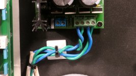
Yeah, I know. It was on oversight. I'm going to fix it.I see untwisted cable pairs lying on the chassis floor.
The mains cables that are not yet connected will also need to be twisted all the way from the transformer winding to the power input socket.
- Status
- This old topic is closed. If you want to reopen this topic, contact a moderator using the "Report Post" button.
- Home
- Source & Line
- Analogue Source
- Doug Self's New Preamp Construction and Pictures