The value i gave where from the VFB( original amp) simulation.
On my CFB, i have 600µa across the R5 1.4k, means 68,55V on the Q7 base, and 69,27V on the emitter. VBE is correct.
With 69.39-69.27 = 120 mv and 12mv at the sides of the R12 10ohms, everything looks perfectly coherent.
We are talking of your schematic , not of the VFB...
")
The current source has 1mA current.
The input stage can not conduct 600uA out of the available 1mA
as the input transistors bases are biased at 0V , so neglecting the base
resistors voltage drop , the input transistors emitters will be respectively
at -0.65V and +0.65V for the NPN and PNP parts respectively meaning that
each 1K feedback resistor will absorb 650uA from the dedicated current source
and 350uA will remain as input stage effective current , hence
the VAS is not biaised correctly as repeated ad nauseam and if
your sims tell otherwise then it means that they are flawed.
Last edited:
My mistake.We are talking of your schematic , not of the VFB...
Please, this is out of topic, can-we discuss this elsewhere ?
Last edited:
Ok, as I said before, devil is in the detail and we have to state matters in a clear and unambiguous manner.What a misunderstanding of closed loop systems !! (stated many times ?)
Let look at a differential VFB amp.
The distortion produced by the +V input will be present in the output.
Here are the two situations, exposed in a "bare-bones manner", ie with only parts of interest explicitly drawn.
First, just the input transistor with a linear FB network having the same resistance as a the dynamic resistance of a similar transistor biased at the same current level.
Q2 and V(A) are only present to simulate an ideal output section of the amplifier. Q2 being biased at a constant, it does not influence the linearity, it is just a convenient level-shifter matched to the amplifier.
V(A) is a spice ideal behavioral voltage source configured as a buffer for the voltage in A (if you don't have faith in spice, you are free to use other methods, they will give the same result).
The THD in this case is 2.3%.
Second pic shows the situation when the second transistor is brought into action.
Now, all the the spice implements are disabled, only the real components operate, with Q2 effective as non-ideal buffer.
The THD is 0.388% (OK, not exactly -20dB, but not that far off, and here I have somewhat exaggerated the current excursion to show something substantial).
I don't ask you to put your faith in spice, but simply to look at the situation explained in a more graphical manner: it seems obvious that Q1 is outside the FB loop, independent of CFB or VFB, and hence, only open loop type compensations methods can have an effect (or a reduced modulation of the Ie current, which is also one of the preferred, but non-exclusive methods).
PS:
Note that there is no cheating, the output amplitudes are similar in both cases (even slightly higher for the "compensated" case)
PPS: you might think that CFB allows for lower equivalent resistances than the dynamic resistance of a feedback transistor; it is true, and it will increase the loop gain beyond what is available in VFB. However, it will also increase the the non-linear fraction of the feedback conductance due to Q1, and will also increase the non-linearity in the same proportion, nulling the effect. It will however improve the rejection of other causes of non-linearity, but that's typical "VFB-speak", and I don't think it appeals much to CFB lovers.
Although some of them seem confused enough to adhere to that proposition....
Attachments
Last edited:
Esperado simulated his CFB crescendo with wrong lateral transistor models. I simulated it with(SSA thread) Cordell models and I had to increase the bias current to get simulation working properly. Distortion was quite low but far from exceptional and not ten times better then VFB, quite the opposite.
dado
dado
I give-it up.
More than 10 people (for those i know) had mail-me to tell they had modified their Crescendo in CFB with similar results.
Pretend Cordel models not good if you like (i have no idea about, but they are reputed)
Argue ad nauseam if you want, provide strange simulations with no open loop gain etc..
Refuse to understand what a proved good designer (L.C.) try to explain to you, with the exact same words than me...
You cannot convince -me from anything else than 40 years of experiments had proved to me.
"N'est pire sourd que celui qui ne veut entendre" "There are none so deaf as those who will not hear".
My sims are not good with the SPICE you use ? (Again, i don't understand why, again i'm too old to be an expert on sims i don't use for my works))
Why don't you make your OWN sims with real amp schematics, comparing VCB against CFB to explore this question and publish your results ?
I give-it up. It will be an endless waste of time. Have a good time.
Last edited:
you can claim anything is "proved" by your ears - but the claim that CFA is inherently better than VFA, with 10x less distortion is a technical question that sims are fine to explore
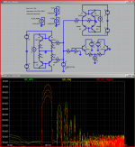
my sim below is complicated by a question of "fairness" - how much degen to use in the CFA input
the usual formulation of a CFA input is no explicit degen, single feedback network - upper right in my sim, yellow trace
the max possible degen with a CFA front end requires 2x feedback dividers as shown in lower left, red trace
and finally the diff pair is shown in the lower right, green trace
all 3 circuits give ~ the same gm from amp Vout within a few %
all of the Q run at the same current
I compare the collector current difference in each circuit
I also stepped the level of V - the highest step of 1 V is an outrageously large Vout error for a high global loop gain amp
the fft is a little hard to read but may yield to a little study - there are 3 stepped polts on top of each other, with 1 V, 100 mV and 10 mV Vout "error" levels
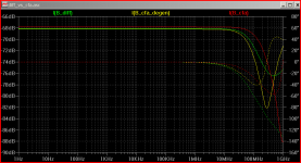
my summary of the results is that for 2nd harmonic VFA (green) is always better than the the standard CFA (yellow), only ~6 dB worse than the max_deg CFA (red)
for odd harmonics the diff pair is worse, substantially worse at higher Verror
the max_degen cfa shares the "bad harmonic structure" of the diff pair with odd harmonics higher than even at similar higher Verror
at low Verror corresponding to high loop gains the max_degen and diff pair front ends have "ideal harmonic structure"
while the plain CFA has "bad harmonic structure"
the speed plot shows that the diff pair falls in between the plain and max_degen cfa, with phase error < 5 degrees to beyond 10 MHz
so if you design "flat loop gain amps" with low loop gain, plain CFA may be better than diff pair or degenerated CFA front ends
but Otala's “flat loop gain” prescription is simply wrong if you accept his TIM/PID "FM" IMD as the important parameter - and early believers like Walt Jung and Marshal Leach changed their minds so it isn't just reactionary deniers not accepting new ideas
with high loop gain diff pair VFA works just fine – with max_degen CFA only ~ 2x “better” - not 10x
my sim below is complicated by a question of "fairness" - how much degen to use in the CFA input
the usual formulation of a CFA input is no explicit degen, single feedback network - upper right in my sim, yellow trace
the max possible degen with a CFA front end requires 2x feedback dividers as shown in lower left, red trace
and finally the diff pair is shown in the lower right, green trace
all 3 circuits give ~ the same gm from amp Vout within a few %
all of the Q run at the same current
I compare the collector current difference in each circuit
I also stepped the level of V - the highest step of 1 V is an outrageously large Vout error for a high global loop gain amp
the fft is a little hard to read but may yield to a little study - there are 3 stepped polts on top of each other, with 1 V, 100 mV and 10 mV Vout "error" levels
my summary of the results is that for 2nd harmonic VFA (green) is always better than the the standard CFA (yellow), only ~6 dB worse than the max_deg CFA (red)
for odd harmonics the diff pair is worse, substantially worse at higher Verror
the max_degen cfa shares the "bad harmonic structure" of the diff pair with odd harmonics higher than even at similar higher Verror
at low Verror corresponding to high loop gains the max_degen and diff pair front ends have "ideal harmonic structure"
while the plain CFA has "bad harmonic structure"
the speed plot shows that the diff pair falls in between the plain and max_degen cfa, with phase error < 5 degrees to beyond 10 MHz
so if you design "flat loop gain amps" with low loop gain, plain CFA may be better than diff pair or degenerated CFA front ends
but Otala's “flat loop gain” prescription is simply wrong if you accept his TIM/PID "FM" IMD as the important parameter - and early believers like Walt Jung and Marshal Leach changed their minds so it isn't just reactionary deniers not accepting new ideas
with high loop gain diff pair VFA works just fine – with max_degen CFA only ~ 2x “better” - not 10x
Attachments
Last edited:
It is really interesting how some people that know electronics much better than me, can not see the simple facts that CF is not only subjectively better, but also in many ways, better circuit in lab parameters.
It is indicative to see what are big semi companies using for the most delicate applications in audio, microphone IC preamps, where ultra low noise and distortion BUT also very high power bandwidth is needed. For instance SSM2017 and INA217 instrumentation OPamps. These ICs are CF! Period!
It is indicative to see what are big semi companies using for the most delicate applications in audio, microphone IC preamps, where ultra low noise and distortion BUT also very high power bandwidth is needed. For instance SSM2017 and INA217 instrumentation OPamps. These ICs are CF! Period!
It is really interesting how some people that don't know electronics very well want simple, 1-dimensional answers like "X" is better than "Y" where each is only a small part of a complete circuit
and some people that claim to know electronic's "sound" are more than willing to pander to them
and some people that claim to know electronic's "sound" are more than willing to pander to them
Last edited:
Trouble is that distortion is not the truth in terms of sonic performance....
This I saw clearly not so long ago where we compared two different takes on 2 simple current feedback amplifiers... one with measured low distortion, and one very similar type but one stage less and much higher distortion. (only difference was in the insertion of a dedicated driver stage) The latter was in all aspects the better performer. more crisp, more transparent, better contrasts. So when you take the simulation route.. you just look at something in steady state.. and that says nothing about the sonic performance.
This I saw clearly not so long ago where we compared two different takes on 2 simple current feedback amplifiers... one with measured low distortion, and one very similar type but one stage less and much higher distortion. (only difference was in the insertion of a dedicated driver stage) The latter was in all aspects the better performer. more crisp, more transparent, better contrasts. So when you take the simulation route.. you just look at something in steady state.. and that says nothing about the sonic performance.
We could also say that "il n'y a de pire corniaud que celui qui refuse de comprendre".Argue ad nauseam if you want, provide strange simulations with no open loop gain etc..
Refuse to understand what a proved good designer (L.C.) try to explain to you, with the exact same words than me...
You cannot convince -me from anything else than 40 years of experiments had proved to me.
"N'est pire sourd que celui qui ne veut entendre" "There are none so deaf as those who will not hear"..
We can introduce loop gain if it feels more familiar.
It will reduce the overall level of distortion (not because of feedback itself, but because the current excursion in the transistor becomes smaller), but it will increase the difference because at low levels, as the compensation between the two non-linear Vbe voltages is more accurate.
Here, an opamp provides the loop gain, and simulates the rest of the amplifier, mainly the VAS, without introducing too much distortion of its own, to avoid obscuring the picture with unrelated distractions.
On the left is the CFB version; the FB divider R12 R13 is not directly connected to the emitter of Q3 because of level translation issues. Q4 drops one constant Vbe, and the resultant voltage is applied to Q3 via an ideal spice buffer (you can trust me, it does what it says, no more no less).
On the right is the VFB version, with the transistors connected in a LTP.
The two output voltages are exactly equal: they are perfectly superposed.
The THD when the input transistor is driven directly is 27ppm, against 1.7ppm when the FB signal is applied through a matched transistor: more than 20dB difference this time.
It is easy to see why the FB has no direct effect on the difference: the non-linear voltage generated in the emitter junction of the transistor is in series with the input voltage, just like an offset or any other error voltage would be: it is therefore amplified, and left untouched by the feedback.
The feedback has an indirect effect, because it allows for a smaller AC voltage across the B-E junction, but this requires loop gain of course, and both configurations benefit from it, meaning the VFB will always keep its ~20dB advantage.
This analysis is valid for the single ended version of CFB, because that was the subject of this part of the discussion.
With a symetrical input, things are different, because the complementary transistors provide a comparable compensation mechanism (although not as good, because the matching cannot be as good as with identical transistors), but this aspect has been investigated by jcx
Attachments
Lazy Cat,
If I decide to build SSA, can I use only 20-30mA bias? I do not have big heatsinks.
That is really minimal bias current per output transistor, optimal would be cca. 150 mA/output device. Calculate power dissipation for bias plus average music power considering 70% of efficiency, I'm sure you have some reserve in heatsinking and could go a bit higher than just 20-30 mA.
At SSA it is also very important to have quiescent Ic: 2-3 mA in input, 10-15 mA in VAS and 20-30 mA in driver stage.
Regards L.C.
Esperado simulated his CFB crescendo with wrong lateral transistor models. I simulated it with(SSA thread) Cordell models and I had to increase the bias current to get simulation working properly. Distortion was quite low but far from exceptional and not ten times better then VFB, quite the opposite.
dado
Check the THD at 20 Khz, its 10 times worse than even the original cresendo.
An other fast and furious example.
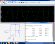
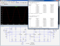
The amp is issued from LTSpice examples. It is called audioamp. I wanted a neutral example.
It measured this at original. Distortion 0.23% bandwidth 70 000hz at-3db.
I tuned the VFB for best simulation results as possible (first image)
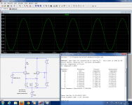
Then modified-it to CFB.and did the same.(second image)
The output level was set precisaly for +-7V peak to peak, and the response curve for no overshoot at HF, as large as possible. Current kept as similar as possible. Nor care for phase margin for both.
As expected, distortion slightly reduced, and bandwidth so dramatically increased in the CFB version (mean IM reduced a lot) that i had to go to the 100Mhz.
of course, it would be unrealistic to expect such a bandwidth in real life, because all the parasitic caps, just to demonstrate by calculations (sim)
The amp is issued from LTSpice examples. It is called audioamp. I wanted a neutral example.
It measured this at original. Distortion 0.23% bandwidth 70 000hz at-3db.
I tuned the VFB for best simulation results as possible (first image)
Then modified-it to CFB.and did the same.(second image)
The output level was set precisaly for +-7V peak to peak, and the response curve for no overshoot at HF, as large as possible. Current kept as similar as possible. Nor care for phase margin for both.
As expected, distortion slightly reduced, and bandwidth so dramatically increased in the CFB version (mean IM reduced a lot) that i had to go to the 100Mhz.
of course, it would be unrealistic to expect such a bandwidth in real life, because all the parasitic caps, just to demonstrate by calculations (sim)
Attachments
Last edited:
0.16 %, vs 0.11 % is hardly conclusive when your ealrier claim was for 10x improvement
you can directly attach .asc files to your post now for us to inspect how "similar as possible" the sim bias settings are
the resistive VAS load assures very low open loop gain - I don't play there for the very good reason that high loop gain is cheap and works better the more you use
http://www.linearaudio.net/images/onlinearticlesPDF/volume1bp.pdf
(Putzeys Linear Audio article is simple, but well written, introduces some of the engineering concepts behind the position that lots of feedback is the only way to use any fedeback)
Last edited:
10 times the bandwith...
distortion is nothing..and tells noting about the sonic qualities on an amp... one here even said that you could just insert a JHL buffer.. as the distortion was lower than the amp it did not matter....
If that has any merit the the amp has no influence as the distortion is 0. zilch compared to the 1000 times higher distortion produced in the speakers... and in speakers distortions say nothing about dynamic capabilities and dynamic unlinearities and noting about mechanical noise and transient compression..
So when looking to distortion as a performance measure.. We simply look at the wrong place... Band-with and slew-rate may be more appropriate figures to look at.. and may be the reason why CFB amps sound better.
Last edited:
I have never pretended real results will show a "X " improvement in HD and alway adverted the numbers was SIMS.0.16 %, vs 0.11 % is hardly conclusive when your ealrier calim was for 10x improvement
you can directly attach .asc files to your post now for us to inspect how "simialr as possible" the sim bias settings are
My real Crescendo amp had a distortion at the limit of my old measuring LEA instruments, from the origin, then when i measured-it, i had just seen HD was reduced, don't know how much, and don't care. I'm more interested with IM, where CFB is all the purpose.
I will not work for you to satisfy the second part of your aggressive asking, with your"inspect" understatement.
I made this experiment as honest as possible, and again, i'm not selling ANYTHING.
R2 current is: 4.724ma in VFB and 4.7245 in CFB
R8 current is: 1.87922 in VFB, and 1.87857 in CFB
Close enough for you ?
I'm tired of this aggressive and suspicious attitude from always the same few contributors.
LTSpice is free, the amp example is given with it, you can pick the printed values and make your sims by yourself, instead asking the others to work for you.
Better, you can begin to experiment by yourself in real world, and try to find the best from Current feedback, you will not regret-it. Or you can believe in what you want and argue at nauseam, i don't care.
That will be my last post in this thread.
Last edited:
10 times the bandwith...
You are gullible...
The two schematics have different settings.
attaching the sim .asc files adds only seconds to your posting - it is simply polite to share the source of sims you are using in a discussion
you were already at the correct forum tool when you attached the images, adding the .asc would have taken only a few mouse clics - probably less than doing the image capture, file saving navigation
saying others should reenter the scheme by hand is deliberately wasting their time - is "passive aggressive" on your part
Last edited:
- Status
- This old topic is closed. If you want to reopen this topic, contact a moderator using the "Report Post" button.
- Home
- Amplifiers
- Solid State
- Is the CFB topology superior, and why?