Look wahab all these guys who likes CFB amps probably started with VFB amp as usual, than probably explore different VFB designes, made different amps from simple to complex VFB topologies, listened, compared, searching continued and one day they heard CFB amp. End of the story.")
I also heard CFB amps of all kind well before it became a fashionism in this forum, yet , it didnt end the story at all.
As for the VFB amps , there are a lot , including in this forum ,
wich are genuine lemons thanks to bad engineering habits ,
so yes , better an average CFB than a badly designed VFB,
although there are also CFB lemons by the tons.
Last edited:
Nico Built the simple SSA and really liked it.
A story from the Arab world :
When all animals reunited , they decided to ask the donkey female
about who has the most beatifull children.
The donkey answered that in all honnesty she found her own children
to be the most awsome.....
All The best amplifiers i have heard has turned out to be CFB.
It seems like those that listens to things come to the same direction. There just seems to be something good/nice about the way the CFB amplifiers work.
"There seems" is just a subjective position.
What is there exactly , as what is audible is forcibly measurable.
Now instead of wonder why and try to find good valid explanation, some people run to the mine is bigger than yours arguments by pulling out the low distortion card, as if that is the only truth. Ok sound perception and musical performance which must be the final goal has diversities and can be challenged for not being objective. But in the end it's the only objective that really matters...!!
The distorsion card as you call it is more than a single card as it
has other meanings that simply THD.
Low THD amps will almost invariably yield low IMD as well , wich is way
more intrusive non linearity and is a better scale than the classical THD
to evaluate an amp s ability to reproduce a signal without re shaping it
musicaly speaking , what we call High Fidelity.
By pulling out the tools we already know we get now where. looking at things with an open mindset may just take you somewhere.
As already said , what is audible is measurable so if an amp
that measure worse sound better then it means that distorsions
can make an amp sound good the same way an aphex aural exciter
make a poor recording sounding good.
Surely that someone having one of thoses amps that sound well
thanks to harmonics enhancement will refuse to aknowledge that
his amp has poor absolute perfs, instead he will say that it sound
good for reasons that are still unknown but not because of its
lack of linearity.
As already said , what is audible is measurable
Yes, what is audible is measurable. But there are many measures, not only THD. Even probably more measures that has not been known to have an audible effect.
so if an amp that measure worse sound better then it means that distorsions
can make an amp sound good the same way an aphex aural exciter
make a poor recording sounding good.
Yes, distortion can make an amp sound good, subjectively. But there are many other measures instead of THD, and there is no one measure/formula that summarize them all.
Which one is better: (A) DF=1, THD=0.001% (B) DF=100, THD=0.01%.
If that is easy (or impossible), can you make it harder by changing the composition? And it is only 2 variables!
Surely that someone having one of thoses amps that sound well
- thanks to harmonics enhancement - will refuse to aknowledge that
his amp has poor absolute perfs,
What is ABSOLUTE performance
And what is harmonics enhancement
I think you have an issue with different tastes regarding second or low or even order harmonics. Why not fill your creative mind with something higher, something that is still "unknown" (instead of trying to look smart around idiots), like Rod Elliot new post regarding inter-modulation of symmetrical versus asymmetrical input signal.
instead he will say that it sound good for reasons that are still unknown but not because of its lack of linearity.
There are many things in audio that is hard to explain scientifically, but the phenomena exist. Same like strange things in life, like meta-physical things (such as how rusted nails can grow inside your body). You can try to explain those using your best ability and your best knowledge about Physics, but those who think they are the real experts in Physics will laugh at you.
There is indeed something about CFB amps that I haven't heard in VFB amps. If you think that this "something" with CFB is related to harmonics (soundwise), I think no, not at all. I think regardless of validity I'm satisfied with my knowledge about this, but I don't want to discuss it because the real experts will laugh.
I believe that those real experts also cannot explain it if they can observe the phenomena. But they can't even observe the phenomena. So it's like they are saying "Prove it if God/Ghost exist, because it doesn't".
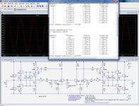
Here is the comparison between the two versions of amplifier from LTspice's examples.
The test conditions have been properly normalized, and the silly impedance levels corrected (at least for the VFB; for the CFB I have kept the values chosen by Esperado, even though they are unusually low).
Some remarks about the way the initial comparison was made: with the very low feedback resistor values, the CFB was in fact on the verge of being VFB: the emitter resistance of the transistor at ~5mA is ~5ohm, with the equivalent resistance of the FB network under 10ohm.
This means it classifies as CFB, but just.
By contrast, the ridiculously high values in the "VFB" version made it in fact CFB too, and even more so than the one that is supposed to be so: the input resistance of the transistor is 800ohm, much less than the FB network.
This means that in fact, the comparison was not between VFB and CFB, but between two half-baked CFB.
Another problem was the level, which was so high that it brought the VAS into presaturation.
The problems have been fixed, at least partially, the levels exactly equalized, and the phase margins have been set at 50°, meaning the comp capacitor is 8.2p for CFB and 22p for VFB.
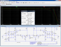
THD is 0.13% for CFB, and 0.107% for VFB. Not striking, because in this amplifier, the main source of distortion is elsewhere: it is shown by the high level of 2nd harmonic, which remains high with the VFB, when it should almost vanish. The poor quasi output stage is to blame.
Next is the bandwidth: the CFB has a -3dB point at 32MHz, against 25MHz for the VFB.
Thus, a moderate improvement, traded for a moderate degradation of linearity.
But the poor performance of the amplifier hides part of the picture; which is why the sim I made earlier concentrated only on the parts of interest: the VFB and CFB cores.
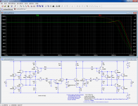
Now, if we want, we can add a degeneration to the VFB to mimic CFB: third pic.
The difference is becoming much smaller, and it is indicative of the true speed penalty brought by the second transistor in the loop.
The test conditions have been properly normalized, and the silly impedance levels corrected (at least for the VFB; for the CFB I have kept the values chosen by Esperado, even though they are unusually low).
Some remarks about the way the initial comparison was made: with the very low feedback resistor values, the CFB was in fact on the verge of being VFB: the emitter resistance of the transistor at ~5mA is ~5ohm, with the equivalent resistance of the FB network under 10ohm.
This means it classifies as CFB, but just.
By contrast, the ridiculously high values in the "VFB" version made it in fact CFB too, and even more so than the one that is supposed to be so: the input resistance of the transistor is 800ohm, much less than the FB network.
This means that in fact, the comparison was not between VFB and CFB, but between two half-baked CFB.
Another problem was the level, which was so high that it brought the VAS into presaturation.
The problems have been fixed, at least partially, the levels exactly equalized, and the phase margins have been set at 50°, meaning the comp capacitor is 8.2p for CFB and 22p for VFB.
THD is 0.13% for CFB, and 0.107% for VFB. Not striking, because in this amplifier, the main source of distortion is elsewhere: it is shown by the high level of 2nd harmonic, which remains high with the VFB, when it should almost vanish. The poor quasi output stage is to blame.
Next is the bandwidth: the CFB has a -3dB point at 32MHz, against 25MHz for the VFB.
Thus, a moderate improvement, traded for a moderate degradation of linearity.
But the poor performance of the amplifier hides part of the picture; which is why the sim I made earlier concentrated only on the parts of interest: the VFB and CFB cores.
Now, if we want, we can add a degeneration to the VFB to mimic CFB: third pic.
The difference is becoming much smaller, and it is indicative of the true speed penalty brought by the second transistor in the loop.
Attachments
Look wahab all these guys who likes CFB amps probably started with VFB amp as usual, than probably explore different VFB designes, made different amps from simple to complex VFB topologies, listened, compared, their search continued and one day they heard CFB amp. End of the story.
I listened to VF amps all my life and I was always perplexed why products with so good specs sound so dull! Most of the time it is sound that passes by the listener, never connecting to the pleasure centers of perception. You can't say exactly what is wrong with VF but listener remains disinterested in musical emotion. I can not say that VF amps are downright bad, they are simply not sounding good enough. They are mediocre.
It has been discussed from the beginning that the differences appear to be the starting points and not the end point. The Vf brings higher non-linearity but a lot of open loop gain to use for correction (via either global or local feedback) compared to the Cf which has lower non-linearity and less gain (which can be increased by the feedback impedance but this is not free).
At the completion of a competent design(s) from both sides it would be surprising if most of the parameters were not nearly identical. Depending on the constraints one approach may be more suited than the other. May be more helpful to dig into the details and try to characterize where each is more appropriate.
The slew rate argument bothers me, I just cant see having more than needed as a benefit especially if its purely a class-ab operation. If the Cf amp really turned off one of the input transistors to get that added current just how far behind the input did it get?
Thanks
-Antonio
There seems to be a consensus that the most signal slew needed for a 100W into 8ohms amplifier is about 5V/us.
If one then adjusts the amplifier to just be able to meet this slewrate then one finds that it distorts.
From experiments it seems that by increasing the amplifiers slew rate up until it is about 10times the maximum signal slew that this added distortion reaches a minimum.
End of consensus.
That seems to imply that 50V/us is required for fast music signals, if one wants to reach that distortion minima for music reproduction..
And increasing beyond the 10times achieves little if anything of an improvement.
Andrew
Indeed, and this would appear to be a result of large signal bandwidth requirements which should be met. That is, is there ever a need to even measure the slew rate of an audio amplifier? I can see where it may serve as an indirect metric and or for diagnostics.
If one could specify requirements for their desired audio amplifier is it appropriate to include slew rate?
Thanks
-Antonio
snip
Your point of view is interesting but since you have some maths formal
training and are used to simulators why not try to check a few claims
and bring a stone to the build that would have way more weight than
subjective assumptions.
Electronics is a science backed field and in this respect it accept
to be questionned with practical experiences so any claim can be
checked and in the subject that interest us CFB supporters still fall
short of proving their claim of so called superiority of this topology
using scientifical yet simple arguments.
There seems to be a consensus that the most signal slew needed for a 100W into 8ohms amplifier is about 5V/us.
If one then adjusts the amplifier to just be able to meet this slewrate then one finds that it distorts.
From experiments it seems that by increasing the amplifiers slew rate up until it is about 10times the maximum signal slew that this added distortion reaches a minimum.
End of consensus.
That seems to imply that 50V/us is required for fast music signals, if one wants to reach that distortion minima for music reproduction..
And increasing beyond the 10times achieves little if anything of an improvement.
What if the input signal is sampled at 192khz like .. often ?That's means that the fastest rise/fall time between 2 consecutive points should be almost 5.2us .
Suposing that the soundcard,dac has a 6volts peak to peak which means exactly 2.1Volts rms as most of the soundcards,dac's has .That means that the SR of the soundcard dac is 6/5.2=1.15V/us .A typical gain of an100W amp is 33. To see the same transition on the amp output we must have the input multiplied with the gain in the same unity time like the input .So if the input has 1.15 V/us ,the output should have 33*1.15~40V/us . This value will be sufficient only if we don't want to have transient intermodulation distortion .But the neagative reaction takes exactly the same time to react to the output .So we should double the value to 80V/us.
But to have a lower TIM we should multiplied with 10
Last edited:
What if the input signal is sampled at 192khz like .. often ?That's means that the fastest rise/fall time between 2 consecutive points should be almost 5.2us .
You did compute the slew rate necessary for a 96khz sine at full power
not for a musical signal wich is limited to a fifth of this frequency so
your 200V/us should translate to 40V/us for a 200W amp , about
the number given by AndrewT.
Is there life ..
There's life above 20 kilohertz! A survey of musical instrument spectra to 102.4 kHz
or more .. http://wilson-benesch.com/reviews/Life_Beyond_20kHz_Blackmer_SVC_Sep-1998.pdf
There's life above 20 kilohertz! A survey of musical instrument spectra to 102.4 kHz
or more .. http://wilson-benesch.com/reviews/Life_Beyond_20kHz_Blackmer_SVC_Sep-1998.pdf
Last edited:
Your point of view is interesting but since you have some maths formal training and are used to simulators why not try to check a few claims and bring a stone to the build that would have way more weight than subjective assumptions.
I'm not a precise person (by psychological test I'm a person who dominantly use the right brain, whatever that means). I mean, you can see that I often mention the wrong things and I still don't care, because it was not the point.
If you are referring to the 10X claim, of course, I have never taken it literally.
And unfortunately I don't rely on simulator to predict the relative quality between two amps of different topologies. Too difficult.
When around 2010 you created that thread about comparing sims of various amps, I thought you would soon learn and realize that it was not that simple. But it seems you still what you were then, fully trust basic simulation parameters to judge amp quality. That's okay of course. I just don't do it that way.
Electronics is a science backed field and in this respect it accept
to be questionned with practical experiences so any claim can be
checked and in the subject that interest us, CFB supporters still fall
short of proving their claim of so called superiority of this topology
using scientifical yet simple arguments.
Yes I think we all knew that. It takes courage to stand and say CFB is superior than VFB
Just like in any other disciplines, some of us know that we have limitations, and at that border line we can just make assumptions, hypothesis, sometimes delusions.Thank you but i know this article.
Unless one listen to 192KHZ sampled crash cymbals at full volume,
assuming he has the speakers for the purpose , the paper
show that harmonics energy is barely more than two percent
of the total amount , so it s unlikely that there will be slew
rate limitation even at thoses frequencies with 30V/us amps....
A story from the Arab world :
When all animals reunited , they decided to ask the donkey female
about who has the most beatifull children.
The donkey answered that in all honnesty she found her own children
to be the most awsome.....
/QUOTE]

Most excellent response.


Thank you but i know this article.
Unless one listen to 192KHZ sampled crash cymbals at full volume,
assuming he has the speakers for the purpose , the paper
show that harmonics energy is barely more than two percent
of the total amount , so it s unlikely that there will be slew
rate limitation even at thoses frequencies with 30V/us amps....
You don't need to listen at full volume to have a peak to peak voltage swing !
Peaks in music are 5 to 10 times higher than the rms value .
in digital audio signal reproduction just "conecting the dots" with straight lines doesn't give a valid audio band limited signal
no commercially distributed musical signals are recorded with substantial 192 k Nyquist content - virtually all studio ADC are delta-sigma and have brick wall internal digital filters below Nyquist
even the hotest source is recorded with slower mics
the vast majority of studio mics have <25 kHz corner frequency, some classic vocal mics may only be 14 kHz
even mc cartridges can only track ~ 5 kHz power bandwidth - when people say records can have higher frequencies than CD you have to realize it is at much lower than mid band amplitudes - the slew rate limit is that ~ 5kHz
no commercially distributed musical signals are recorded with substantial 192 k Nyquist content - virtually all studio ADC are delta-sigma and have brick wall internal digital filters below Nyquist
even the hotest source is recorded with slower mics
...
recorded music is band limited – Earthworks' fastest recording mics are limited to 50 kHz – and they have such poor S/N that their only use is close micing drum kit – capturing sound that never reaches the audience ears in reasonable live venues
and that 50 kHz is still a small fraction of the closed loop bandwidth of typical modern audio power amps
...
the vast majority of studio mics have <25 kHz corner frequency, some classic vocal mics may only be 14 kHz
even mc cartridges can only track ~ 5 kHz power bandwidth - when people say records can have higher frequencies than CD you have to realize it is at much lower than mid band amplitudes - the slew rate limit is that ~ 5kHz
And unfortunately I don't rely on simulator to predict the relative quality between two amps of different topologies. Too difficult.
What would be easier and more accurate ? Design by ears ?..
When around 2010 you created that thread about comparing sims of various amps, I thought you would soon learn and realize that it was not that simple. But it seems you still what you were then, fully trust basic simulation parameters to judge amp quality. That's okay of course. I just don't do it that way.
Processors with roughly one billion transistors are first simulated
and they work wich is the prove that simulators are accurate enough
to model real world behaviour of very complex electric devices , but still , here , there s lot of people that think that it s up to them to predict
the behavior of basic circuits using a handfull devices.
Indeed , had the sims displayed a superiority of CFB that its
promoters would have gladly embraced the conclusions
without even checking but alas , nothing of the sort did
happen , so what is left is to brand the simulations as not
significant....
sure you can model what the circuits do, but not how they sound....simple as that...!!!
Some of the fine amplifiers out there are based on tubes where you measure maybe 1% distortion, speakers are also measured in % and here we talk about 0.00something. It's pure nonsense..performance is not about distortion, something else is just much more important.
CFB finds that something more often than VFB.. Question remains what and why...??
Quite sure simulators can find that difference too, and that could be the key to unlock more knowledge. but arguing in a way "I know more than you do" will never get us there.
To gain knowledge we have to remain open and listen. Most here have something to contribute.. A least for me CFB is more than fashion. but in the End It may not be the final solution.
- Status
- This old topic is closed. If you want to reopen this topic, contact a moderator using the "Report Post" button.
- Home
- Amplifiers
- Solid State
- Is the CFB topology superior, and why?