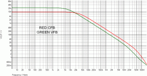
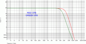
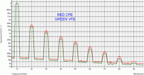
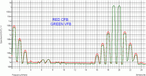
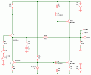
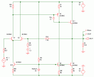
0.16 %, vs 0.11
At first look we can see that the VFB tail current is unbalanced,
hence , its distorsion will forcibly be increased.
Also , the CFB has ideal emitter current load while the VFB
emitter current is provided by a 1K resistor , a way to increase
drasticaly the distorsion compared to the use of even an average
real world current source.
I will stop there since erroneous protocols are used in comparisons
that will be inherently flawed.
What is the use of higher BW and SR if it doesnt reduce non linearities..??..
Our perception of distorsion is well above our perception of bandwith
or slew rate that are indeed source limited.
If the source has maximum 1V/uS slew rate and that an amp has 20 gain
then no matter how fast is the amp , the max output slew rate will be 20V/uS ,
so improving the amp SR and BW will not change the output signal shape by a iota.
The only difference higher SR and BW could make is lower distorsions thanks
to eventual higher NFB at high frequency , but alas , it doesnt materialize at all
for obvious reasons.
now an good amplifier is a bit like driving a strong racy car.. even when you go 80kmt... you still sense the power and agility..
your look back to distortion.. that does not matter... we simply look at something so insignificant compared to other things. You simply say higher slew-rate and bandwidth is an non issue as it does not transcend into lower distortion...
Why is then distortion a valid performance criteria..??? It tells you nothing about the dynamic behaviour of the amplifier... it's static and steady state. A non value. for sonic performance.
Non informed dyiers have the perception that a high SR amp will increase
dynamics but that s a totaly wrong assumption.
It s not the amp that sets the dynamicity but the source ,
the same way that if a source produce a signal with 1% THD then
no matter if the amp has intrinsical THD at 1ppm , the output signal will
still have those 1% THD.
dynamics but that s a totaly wrong assumption.
It s not the amp that sets the dynamicity but the source ,
the same way that if a source produce a signal with 1% THD then
no matter if the amp has intrinsical THD at 1ppm , the output signal will
still have those 1% THD.
MiiB, you've been here long enough to know the arguments so your "query" sounds like an indirect way of beating a moldy strawman
sine waves are "dynamic" - they have time derivatives of all orders
they make great test test signals because they concentrate the distortion products in easily separated harmonics
and to a large degree our audio neural processing seems to use frequency as a basis - as does much of our music which is tonally based
recorded music is band limited – Earthworks' fastest recording mics are limited to 50 kHz – and they have such poor S/N that their only use is close micing drum kit – capturing sound that never reaches the audience ears in reasonable live venues
and that 50 kHz is still a small fraction of the closed loop bandwidth of typical modern audio power amps
Cordell advocates THD 20 KHz near full output test tone as sufficiently dynamic, stressing to an audio power amp - 1 kHz THD isn't usually as revealing of amp defects
we could add multitone IMD plots - I do so regularly in my sims
in principle any periodic waveform can be made of multitones - do I need to point to the many refutations of the Sophomoric "time domain is fundamentally different that frequency domain" memes that keep cropping up
what "single event" “dynamic”, “transient”, “time domain” audio, music signal repeated at seconds, minutes is going to give different audio amp response from one repeated days later?
Last edited:
Looking at Esperado s sims , there s even more obvious errors in the test
protocols in that the schematics caracteristics are not the same for CFB
and VFB , particularly very important parameters that are the generator
and the NFB network output Z wich differ greatly in the schematics.
Yet , thoses output Z are instrumental for the circuits frequency responses,
and in this regard , while the CFB is granted a 10R output impedance generator
the VFB has a 5K (yes 5000R...) output Z generator , a total nonsense
if bandwith is to be simmed in equal conditions.
No wonder that a 10X frequency response ratio was displayed in theses flawed sims.
Moreover , the CFB has a NFB network output Z of 10R while the VFB
has a 5K output Z NFB network , wich will greatly increase the Q of
the return path , commanding more energic compensation and reducing
the closed loop bandwith.
Once we put the circuits in genuines conditions the pictures start
to be more visibles.
Overall the CFB has double the bandwith but half the linearity ,
wich was to be expected since the VFB has double the OLG.
The slightly higher speed of the CFB doesnt translate in better
linearity , this is the contrary , as one can not have "le beurre
et l argent du beurre" ( either the butter or the money it is worth but
not both at the same time).
Since frequency response and linearity were the parameters at stake
i didnt go further for the time but we can assume confidently that
for other parameters such as PSRR , CMRR and so on the CFB will
be inferior by quite a margin.
Anyway , this show that simulators in the hand of either non informed
or biaised people can be bended to show things that are at odd with reality
and unfortunately a lot of people falls in theses traps and will put much
efforts to build projects that are not mastered and whose caracteristics
are at best average but whose promoters have quite a lot of skills
in the entertaining department.....
I made the prove that your schematics were not equivalent and as a consequence
that your sims are flawed but since you have no valuable technical point you re eluding
the discussion by transposing it in a personnal opposition as a mean to downplay
the fact that you have not a good understanding of the very schematics you
used to "prove" your point.
A good education would be to check the results rather than denigrating.....
Edit : The post i m responding to in this one has just disapeared....
Nevermind , the sims and schematics used.
Attachments
Last edited:
Last exception of my promised silence here.
The impedance of your feedback is not accurate for a CFB, and your compensation has no reason to be here. Just to limit the bandwidth for your demonstration (witch reveal despite all your efforts a better bandwidth)..
A CFB lie on high OLG, low impedance FeddBack (you know, "current" ?). it is a elementary BASIS !
While VFB need the differential stages to be balanced in impedance (you know "voltage" ?).
To answer on the same tune that your previous posts, your CFB is just a bad designed amp looking like a CFB.
A prove...not experienced... biased...bla bla.
Please, read all that was published about this subject since decades.
Last edited:
The impedance of your feedback is not accurate for a CFB, and your compensation has no reason to be here.
Just to limit the bandwidth for your demonstration (witch reveal despite all your efforts a better bandwidth)..
You didnt even notice that there s no compensation on the CFB ,
only on the VFB....
So much for your arguments...
It s not the CFB whose bandwith is reduced , it s the VFB whose bandwith
is no more castrated by a 5K output Z for the generator and NFB path ,
as was the case in your phony sims.
A CFB lie on high OLG, low impedance FeddBack (you know, "current" ?). it is a elementary BASIS !
See above , talking of lies.....
Last edited:
Non informed dyiers have the perception that a high SR amp will increase
dynamics but that s a totaly wrong assumption.
It s not the amp that sets the dynamicity but the source ,
the same way that if a source produce a signal with 1% THD then
no matter if the amp has intrinsical THD at 1ppm , the output signal will
still have those 1% THD.
I cannot agree with you at all. By the way what is dynamicity. Talking about non informed DIYers
From what you say an amp capable of 1 watt and noise floor of 0.001 watt has the same dynamic range as an amplifier with output 100 watt and 0.001 watt noise floor. No way!
Besides having a higher dynamic range it will also be more linear and reveal less distortion over a similar bandwidth, since all these artifacts are related to third order intercept. Why bring input distortion into the equation, then we may as well disregard amplifier THD like MiiB suggests completely as the distortion of the very first stage, the recording on CD will be the deciding factor in the overall system performance.
Last edited:
From what you say an amp capable of 1 watt and noise floor of 0.001 watt has the same dynamic range as an amplifier with output 100 watt and 0.001 watt noise floor. No way!
How can you reach such a conclusion since i said that higher slew rate will not improve dynamicity.
Did i mention power or noise floor ?...
So you re doing conclusions from something that i didnt say at all and then goes
to prove me wrong....
Dynamic range is of course related to SN ratio and power output but not to slew rate,
yet i read here and there that amps with high slew rates have better dynamic , wich
is not a well informed opinion , you can easily agree on this latter point..
Last edited:
Ok why don't we just continue to do what we always have done... really like the development in that... In everything sonic performance matter in the end. and I guess we all get the results we need.
In this forum everything becomes an argument. and theres no acceptance of the strengths the different approaches brings to the table.
In this forum everything becomes an argument. and theres no acceptance of the strengths the different approaches brings to the table.
In this forum everything becomes an argument. and theres no acceptance of the strengths the different approaches brings to the table.
There s no way that an eventual strengnth of a circuit is not accepted,
one would be crazy if he did choose a circuit according to the schematic
aesthetics or hyped promotion.
The problem lies elsewhere.
Since a few of us do not take things at face value , whoever make extraordinary claims must
accept to have his claims challenged technicaly speaking and should prove his points using scientific
protocols.
Unfortunately , there are people who refuse to abide by scientific rules ,
yet they will use sound terms when speaking of their preferences ,
wich is a way to give some thickness to an otherwise hollow discourse.
There was a time when such pseudo theories, as Otala s amp s requirements
to reduce TIM , could quietly make their way through the audio community
because at the time there was no simulators and proving that something was wrong
did mandate dealing with quite complexe and lenghty mathematical
equations that few would have checked unless they were put on a payroll
for this purpose.....
Last edited:
The fact is-
"CFB is best for music amplification, worst for online discussion".
Yet another scientificaly proved assumption......
Slogans as an argument , that does say it all.
Indeed , CFB builders rely in entertainement and hype and your post
just follow this path.
Last edited:
This thread reminds me of Martin Collom's text describing the process of designing a product at Conrad Johnson. They tried different NFB settings and ended up with no FB at all! The importance of distortion figures for audio amps is probably overestimated. This is direct result of progressive materialism ideology of the West. Every progress must be rendered in statistical terms.
But the beauty of CF is that you can have both excellent specs AND great sound. That is why I like it so much.
But the beauty of CF is that you can have both excellent specs AND great sound. That is why I like it so much.
But the beauty of CF is that you can have both excellent specs AND great sound. That is why I like it so much.
No one dispute the fact that it can be good enough , what is disputed
are extraordinary claims that do not hold once they are questionned
but instead of answering using technical arguments some CFB builders
that hangs by there will purpotedly displace the debate , most notably
by arguing that i , with others , do not find CFBs to be good while we said
that they are no better and often worse , backing our claims with technical
explanations.
Contrary to the opposition i simulated all schematics that were built
in this forum , including variants wich are still not used.
IIRC , in the SSA thread some asked for the CMRR of this amp ,
yet , no one did provide an answer while i soon checked the thing
and still waiting for the builders findings in this matter...
But surely that it sound good enough , so it surely has 1000dB CMRR ,
or if not the case , it cant be worse than a VFB.....
Look wahab all these guys who likes CFB amps probably started with VFB amp as usual, than probably explore different VFB designes, made different amps from simple to complex VFB topologies, listened, compared, their search continued and one day they heard CFB amp. End of the story. 
The fun s in the wonder and the skizma that we may be looking at the wrong measures...
Nico Built the simple SSA and really liked it. All The best amplifiers i have heard has turned out to be CFB.
It seems like those that listens to things come to the same direction. There just seems to be something good/nice about the way the CFB amplifiers work. Now instead of wonder why and try to find good valid explanation, some people run to the mine is bigger than yours arguments by pulling out the low distortion card, as if that is the only truth. Ok sound perception and musical performance which must be the final goal has diversities and can be challenged for not being objective. But in the end it's the only objective that really matters...!!
By pulling out the tools we already know we get now where. looking at things with an open mindset may just take you somewhere.
- Status
- This old topic is closed. If you want to reopen this topic, contact a moderator using the "Report Post" button.
- Home
- Amplifiers
- Solid State
- Is the CFB topology superior, and why?
